Process for producing wire-grid polarizer, and liquid crystal display device
a liquid crystal display device and wire-grid technology, applied in the direction of polarizing elements, instruments, optical elements, etc., can solve the problems of insufficient suppression of s-polarized light reflection at the liquid crystal panel side, low productivity, etc., and achieve high p-polarized light transmittance, high productivity, and high degree of polarization
- Summary
- Abstract
- Description
- Claims
- Application Information
AI Technical Summary
Benefits of technology
Problems solved by technology
Method used
Image
Examples
first embodiment
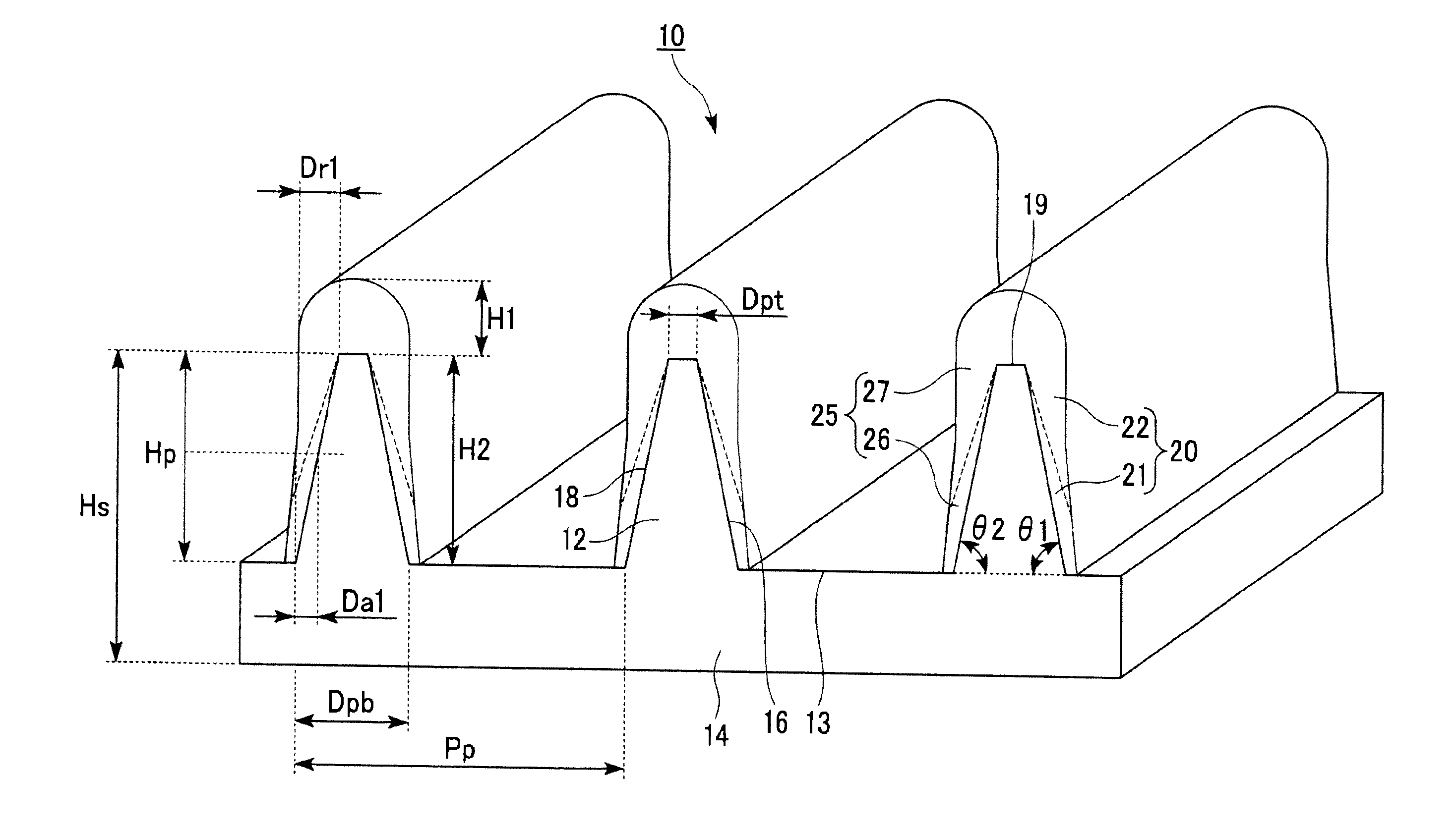
[0109]FIG. 1 is a perspective view showing a first embodiment of the wire-grid polarizer produced by the process of the present invention. A wire-grid polarizer 10 has a light-transmitting substrate 14 having a surface on which a plurality of ridges 12 each having a trapezoidal cross-section are formed in parallel with one another at a predetermined pitch Pp with flat portions 13 of grooves formed between the ridges 12; a metal oxide layer 21 covering the entire surface of a first side surface 16 of each ridge 12; and a metal layer 22 formed on a surface of the metal oxide layer 21 from the half-height position to the top portion 19 and on the top portion 19 of each ridge.
[0110]The cover layer is constituted by a first cover layer 20.
[0111]The first cover layer 20 is constituted by the metal oxide layer 21 and the metal layer 22, and the maximum value of the covering thickness from the half height position to the bottom portion of each ridge 12 is smaller than the maximum value of t...
second embodiment
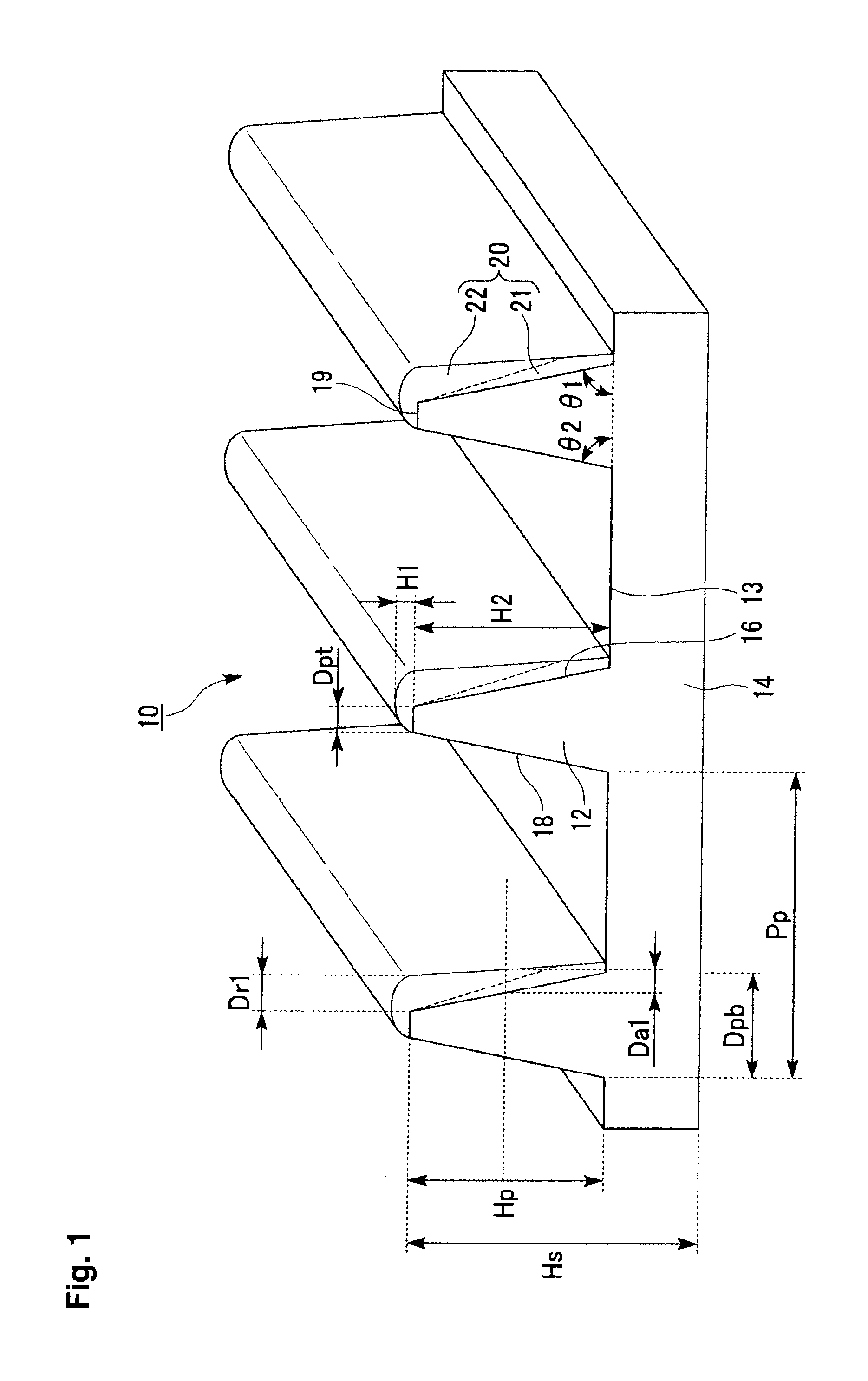
[0125]FIG. 2 is a perspective view showing a second embodiment of the wire-grid polarizer produced by the process of the present invention. A wire-grid polarizer 10 has a light-transmitting substrate 14 having a surface on which a plurality of ridges 12 each having a trapezoidal cross-section are formed in parallel with one another at a predetermined pitch Pp with flat portions 13 of grooves formed between the ridges 12; a metal layer 22 covering the entire surface of a first side surface 16 of each ridge 12, and a metal oxide layer 21 formed on a surface of the metal oxide layer 21 from the half-height position to the top portion 19 and on the top portion 19 of each ridge.
[0126]The cover layer is constituted by a first cover layer 20.
[0127]The first cover layer 20 is constituted by a metal layer 22 and a metal oxide layer 21, and the maximum value of the covering thickness from the half height position to the bottom portion of each ridge 12 is smaller than the maximum value of the ...
third embodiment
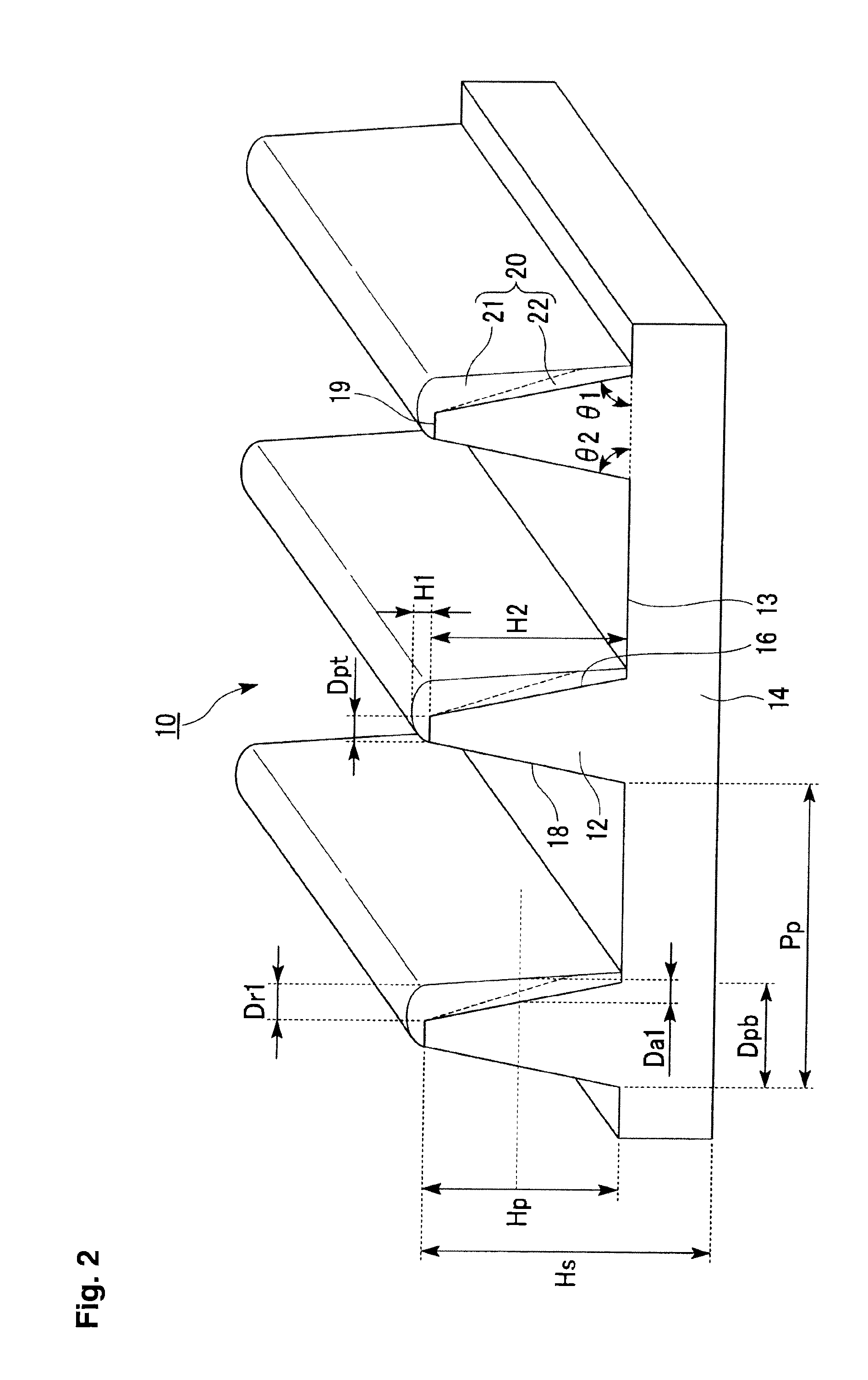
[0130]FIG. 3 is a perspective view showing a third embodiment of the wire-grid polarizer produced by the process of the present invention. A wire-grid polarizer 10 has a light-transmitting substrate 14 having a surface on which a plurality of ridges 12 each having a trapezoidal cross-section are formed in parallel with one another at a predetermined pitch Pp with flat portions 13 of grooves formed between the ridges 12; a metal oxide layer 21 covering the entire surface of a first side surface 16 of each ridge 12, and a metal layer 22 formed on a surface of the metal oxide layer 21 from the half-height position to the top portion 19 and on the top portion 19 of each ridge; a metal oxide layer 26 covering the entire surface of a second side surface 18 of each ridge 12; and a metal layer 27 formed on a surface of the metal oxide layer 26 from the half-height position to the top portion 19 and on the top portion 19 of each ridge.
[0131]The cover layer is constituted by a first cover lay...
PUM
| Property | Measurement | Unit |
|---|---|---|
| thickness | aaaaa | aaaaa |
| angle | aaaaa | aaaaa |
| height | aaaaa | aaaaa |
Abstract
Description
Claims
Application Information
 - R&D
- Intellectual Property
- Life Sciences
- Materials
- Tech Scout
- Unparalleled Data Quality
- Higher Quality Content
- 60% Fewer Hallucinations
Browse by: Latest US Patents, China's latest patents, Technical Efficacy Thesaurus, Application Domain, Technology Topic, Popular Technical Reports.
© 2025 PatSnap. All rights reserved.Legal|Privacy policy|Modern Slavery Act Transparency Statement|Sitemap|About US| Contact US: help@patsnap.com


