
Apparatus and method for performing radiation energy treatments

a radiation energy treatment and apparatus technology, applied in radiation therapy, medical science, therapy, etc., can solve the problems of varying the angle between the discharge end of such wand-like devices and the surface exposed, the most difficult to accurately control, and the area exposed to laser energy

Inactive Publication Date: 2013-02-14
SIEGEL JERRY
View PDF4 Cites 22 Cited by
  • Summary
  • Abstract
  • Description
  • Claims
  • Application Information

AI Technical Summary

Benefits of technology

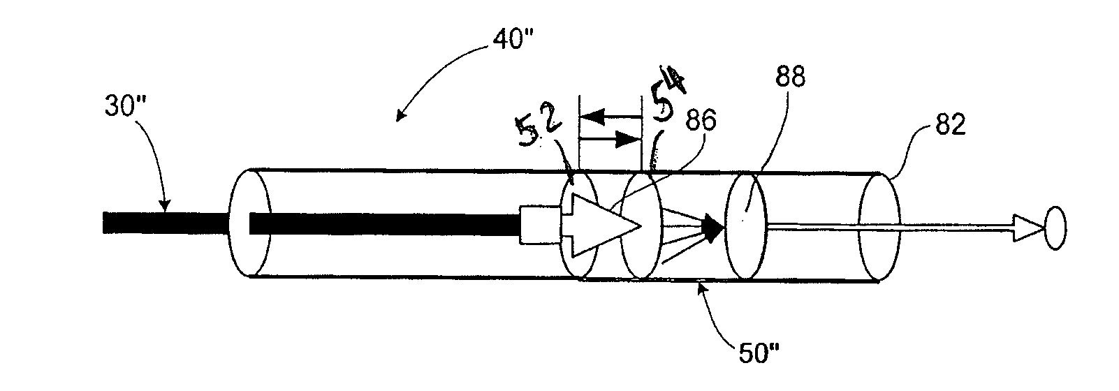
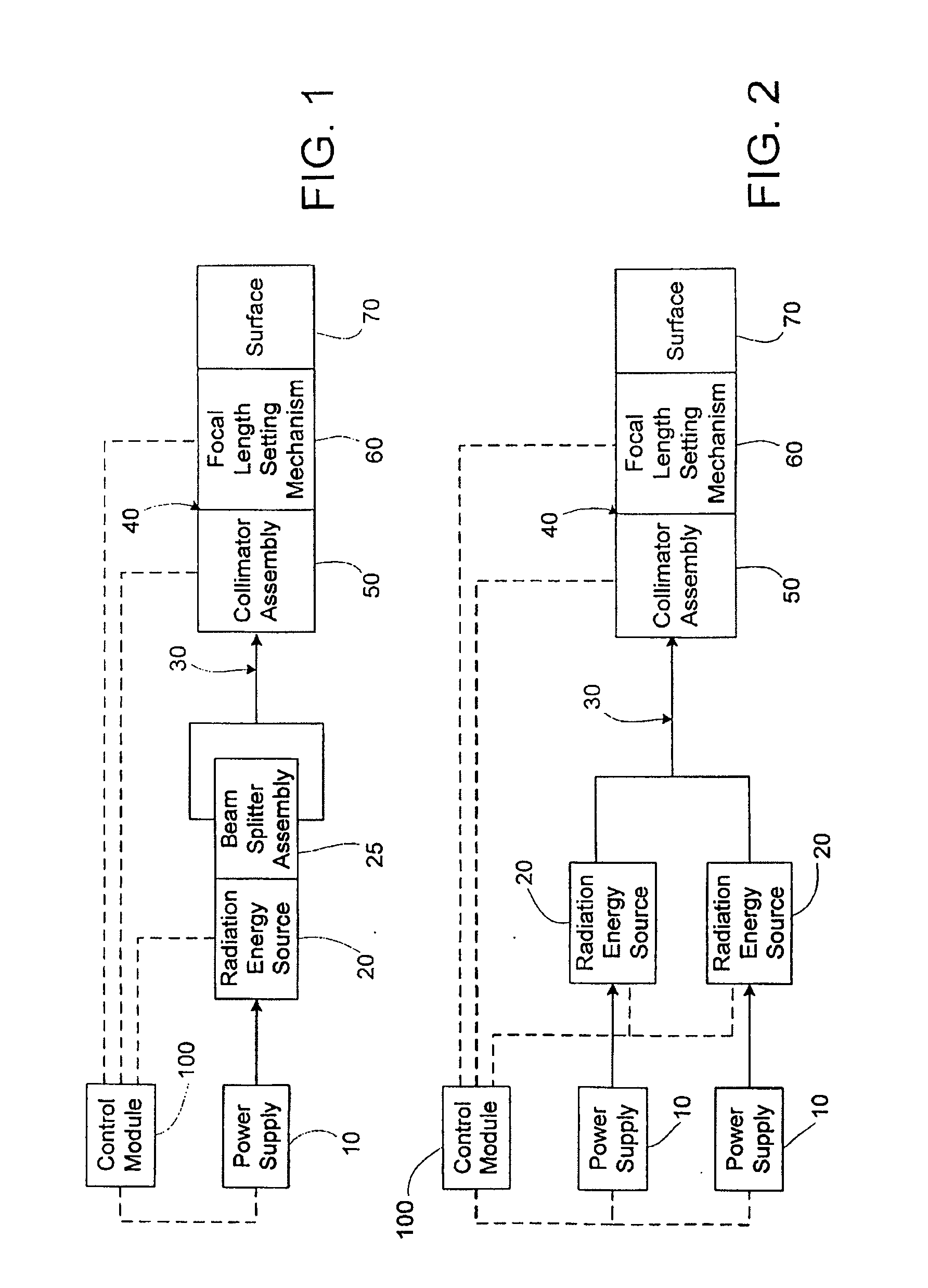
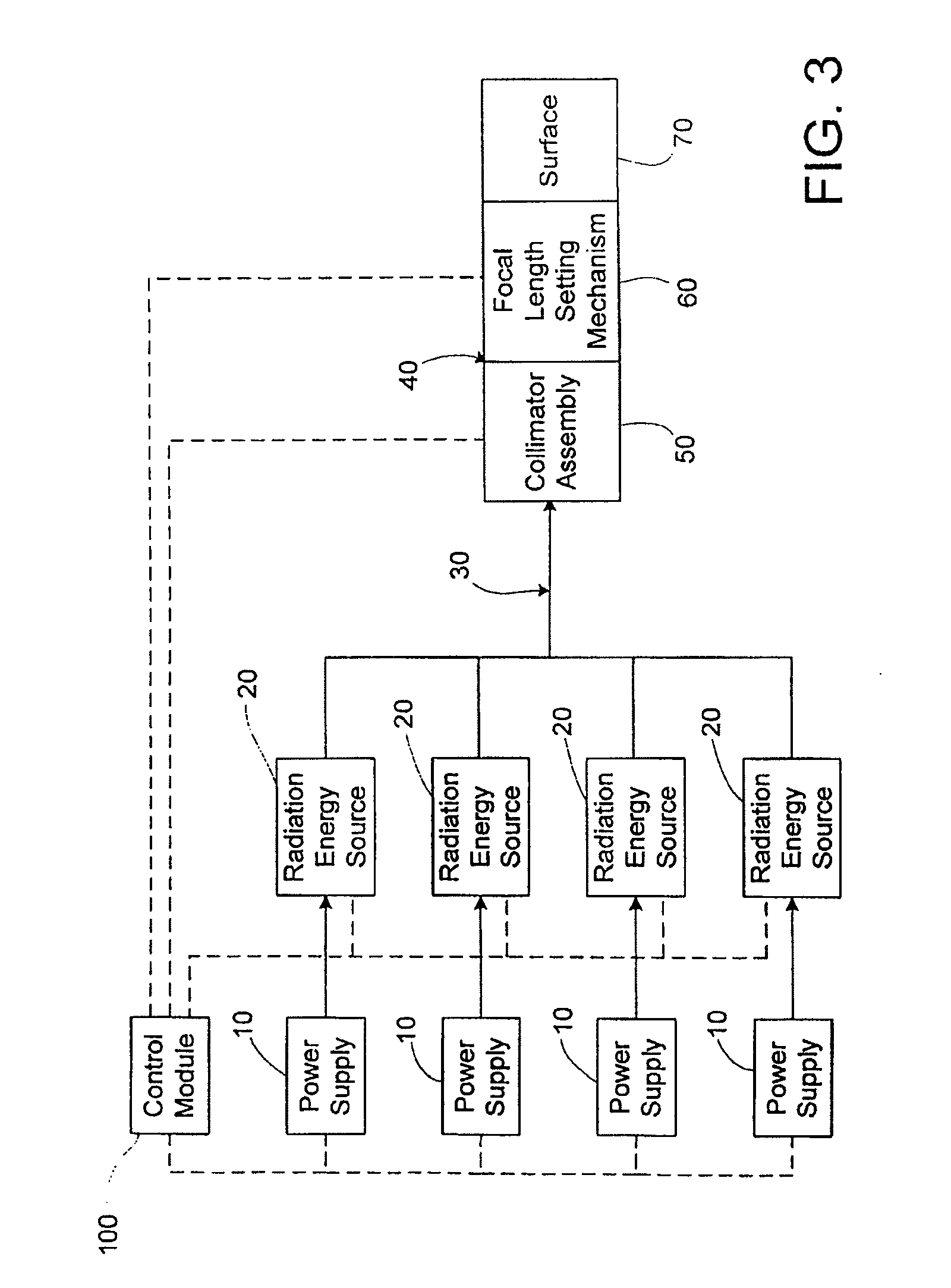
The present invention is about a device and method for non-invasive and invasive radiation energy treatments on biological tissue. The device includes a collector assembly, collimator assembly, and focal length setting mechanism to selectively emit radiation towards the tissue. The invention provides a variety of specific energy densities and wavelengths for different treatment ranges and over larger areas. The emitted radiation is directed to the tissue through a transmission assembly that includes fiber optic cables that must be precisely controlled for the amount and wavelength of the radiation emitted. The invention also includes an adjustable collimator assembly to securely set a desired focal length of the emitted radiation relative to the tissue. Overall, the invention allows for efficient and precise treatment with a single device.

Problems solved by technology

In addition to the variability present in laser energy output and energy wavelength, perhaps the most critical variable in the medical application of laser beams, and among the most difficult to accurately control, is the energy density at the point of exposure of the biological tissue.
Even in the hands of the skilled medical laser operator, however, the distance and angle between the discharge end of such wand-like devices and the surface exposed are not precisely maintained, therefore, the area exposed to the laser energy often varies.
Further, even when a fixed laser beam is employed, control of the area exposed is difficult and imprecise.
First, the patient must be positioned the exact and correct distance from the laser beam to define the area of exposure, which is difficult to do with precision due to the distance between the laser beam and the patient.
In addition, the patient must be positioned such that the area exposed is at the correct angle relative to the fixed laser beam, again being difficult to do with precision due to the distance between them.
As may be appreciated, the control of the area exposed, and thus, the energy density to which biological tissue is exposed, by either of the above techniques is difficult at best.
Indeed, partly for this reason, known systems are configured to only treat very small areas, making the procedures very time consuming and as a result, more susceptible to error.
Furthermore, no one has described an apparatus that incorporates a device that comprises a collector with a reflecting lens that collects and then redirects the scattered and reflected radiation back to the site of treatment while utilizing either a single collimator or multiple collimators that are targetable and focusable and that include an adjustable focal length mechanism that emit coincident visible and infrared radiation, that can either intersect inside the targeted tissue or deploy in series upon the tissue, wherein the infrared radiation has a wavelength of approximately 1100 nm.

Method used


Image

  • Apparatus and method for performing radiation energy treatments
  • Apparatus and method for performing radiation energy treatments
  • Apparatus and method for performing radiation energy treatments

Examples


example 1

[0093]As an example, referring to the second row of the table of FIG. 15, to treat a malady of a tendon injury or tendon tear, the radiation energy of from about 1 to about 7500 mW is applied to the patient for from about ten to about 1200 seconds. The contact area to which the radiation energy is applied to the patient is from about 2 cm2 to about 6 cm2 and the laser is applied as a constant wave of 100%. The pulsed duty cycle of the applied energy is from about 1% to about 200 cycles, and the cadence is from about 0 to 33 Hz. The radiation wavelength is 630, 980, 1060 and 1064 μm, and the treatment energy density is from about 0.1 to about 2000 Joules per square centimeter.

[0094]Examples 2-33 of use of the apparatus disclosed herein and of treatment of a patient are presented, respectively, in rows 3-34 of FIG. 15. Note that there is a table heading “Systemic Viral Infections” following Example 26 (Onichomychosis). Also, there is a heading “Auto Immune System” preceding Example 29...

example 34

Pain Attenuation

[0099]In one embodiment of treatment for Pain Attenuation a wavelength 808-1064 nm is used for deeper penetration and higher absorption rate of photons from the laser light energy. The practitioner applies the treatment to the prescribed acupuncture sites at a dose of (5 J / cm2) at a 2 cm spot size and then lasers the entire site for 2 minutes CW for 2 times a week for a period of 8 weeks.

example 35

TMJ

[0100]In one embodiment for the treatment of TMJ the practitioner treats the patient 2 times a week for a period of 10 weeks at (830-1064 nm) laser wavelength @ (40 S, CW, 500 Mw, 100 j). The practitioner applies the treatment to the prescribed acupuncture site at a 2 cm spot size. This is performed twice and then the entire TMJ joint is treated for 120 Seconds at CW at 2000 mw with a spot size of 3 cm moving the hand piece in a circular motion as not to injure the surface tissue.


PUM


Abstract

Method to apply photo-stimulation, photo-dynamic therapy and / or ablation laser treatment to biological tissue including directing radiation from at least one radiation energy source for supplying a treatment radiation; adjusting a collimator assembly for directing radiation from the at least one radiation energy source to the treatment site; collecting radiation not absorbed at the treatment site and reflecting the radiation back to the treatment site, while a contact surface of the collector is engaged with the surface of the biomass; maintaining a set distance between the adjustable collimator assembly and the contact surface; and moving a lens relative to an outlet aperture of the adjustable collimator assembly when the collector is adjusted to thereby produce a given spot size, shape or energy density of the treatment radiation emitted from the adjustable head assembly.

Description

RELATED APPLICATIONS[0001]This application is a continuation-in-part of U.S. application Ser. No. 11 / 612,385, filed Dec. 18, 2006, which is a continuation-in-part of U.S. application Ser. No. 10 / 227,106 filed on Aug. 23, 2002, which claims the benefit under 35 USC 119(e) of earlier filed U.S. Provisional Application Ser. No. 60 / 314,938, filed on Aug. 23, 2001, all of which are hereby incorporated herein by reference in their entireties.FIELD OF THE INVENTION[0002]The present invention is directed to an apparatus and a method for performing radiation energy treatment on a target area of biological tissue, wherein the apparatus for performing radiation energy treatments on biological tissue is structured to provide a plurality of laser energy treatments comprising of at least but not limited to ablation, biostimulation, photo-stimulation, photocollegan regeneration, and photo-dynamic therapy, either separately or in conjunction with one another, utilizing low, medium, and / or high powe...

Claims


Application Information

Patent Timeline
Patent Type & Authority Applications(United States)
IPC IPC(8): A61N5/067A61B18/20A61M37/00
CPCA61N5/0616A61N5/062A61B18/203A61N2005/0644A61B2018/207A61N2005/063A61B2018/00452
Inventor SIEGEL, JERRY
Owner SIEGEL JERRY
Learn More