Laser generation of narrowband lamb waves

a lamb wave and laser technology, applied in the field of non-contact, can solve the problems of inability to detect defects and discontinuities in real time, non-contact ultrasonic sensing, and methods that are not suitable for automated real-time inspection during manufacture, so as to reduce signal complexity, reduce signal complexity, and allow flexibility in wavelength selection

Inactive Publication Date: 2013-02-28
GEORGIA TECH RES CORP
View PDF8 Cites 8 Cited by
  • Summary
  • Abstract
  • Description
  • Claims
  • Application Information

AI Technical Summary

Benefits of technology

[0013]Embodiments of the present invention can comprise a system and method for providing laser generated, narrowband Lamb waves utilizing various techniques, including, but not limited to, superimposed line sources, Fourier transforms, and wavelet transforms. The system and method can generate narrowband Lamb waves with a dominant wavelength by superimposing signals of line sources at the pitch corresponding to the desired wavelength. The superposition can be performed in software after data are collected to permit flexibility in the wavelength selection. Selecting the dominant wavelength in signals can reduce signal complexity and the speeds and frequencies of wave modes with the selected wavelength can be determined using dispersion curves. One or more additional techniques can be used to further reduce the complexity of the signals. The system and method can be used, for example, for defect detection in thin plates.

Problems solved by technology

Due to the need for liquid couplants between the PZTs and the sample, however, this method is not suitable for automated real-time inspection during manufacture.
Non-contact ultrasonic sensing, on the other hand, has the potential to detect defects and discontinuities in real time.
When the thickness of the sample approaches the wavelength of the ultrasonic wave, however, this method no longer provides accurate data.
Laser generated ultrasound is broadband in nature, however, and this, combined with the dispersive nature of Lamb waves, makes signal processing complicated.
Shadow masks, depicted in FIG. 2a, are economical, fairly effective and easy to implement (hereinafter referred to as “pattern source”), but they are not flexible and have several disadvantages.
These include, but are not limited to, the need to fabricate different masks for each different wavelength of interest, the absorption of a substantial amount of energy by the mask, and the inability to practically manufacture masks with very small spacing.
In addition, because the masks must be manually changed for each separate wavelength, experimental setup for masks for a large number of wavelengths can be impractical.

Method used


Image

  • Laser generation of narrowband lamb waves
  • Laser generation of narrowband lamb waves
  • Laser generation of narrowband lamb waves

Examples


example 1

[0045]To compare the efficacy of the SLS method versus the conventional pattern source method two preliminary experiments were conducted on a 300×200×2 mm aluminum plate. FIGS. 2a and 2b show the schematic of the experiment and the placement of the sensors and the sources for the conventional pattern source (FIG. 2a) and the SLS (FIG. 2b), respectively. FIG. 2a depicts the experiment using a pattern source 220 where the laser beam 205 goes through a mask 210 with eight slits 215. Each slit 215 is 1 mm wide and 15 mm long and the pitch between slits 215 is 2 mm. Also shown is a laser mark 237 of the pattern source 220 on the laser alignment paper 235. The width of each stripe is about 1 mm and the pitch is 2 mm.

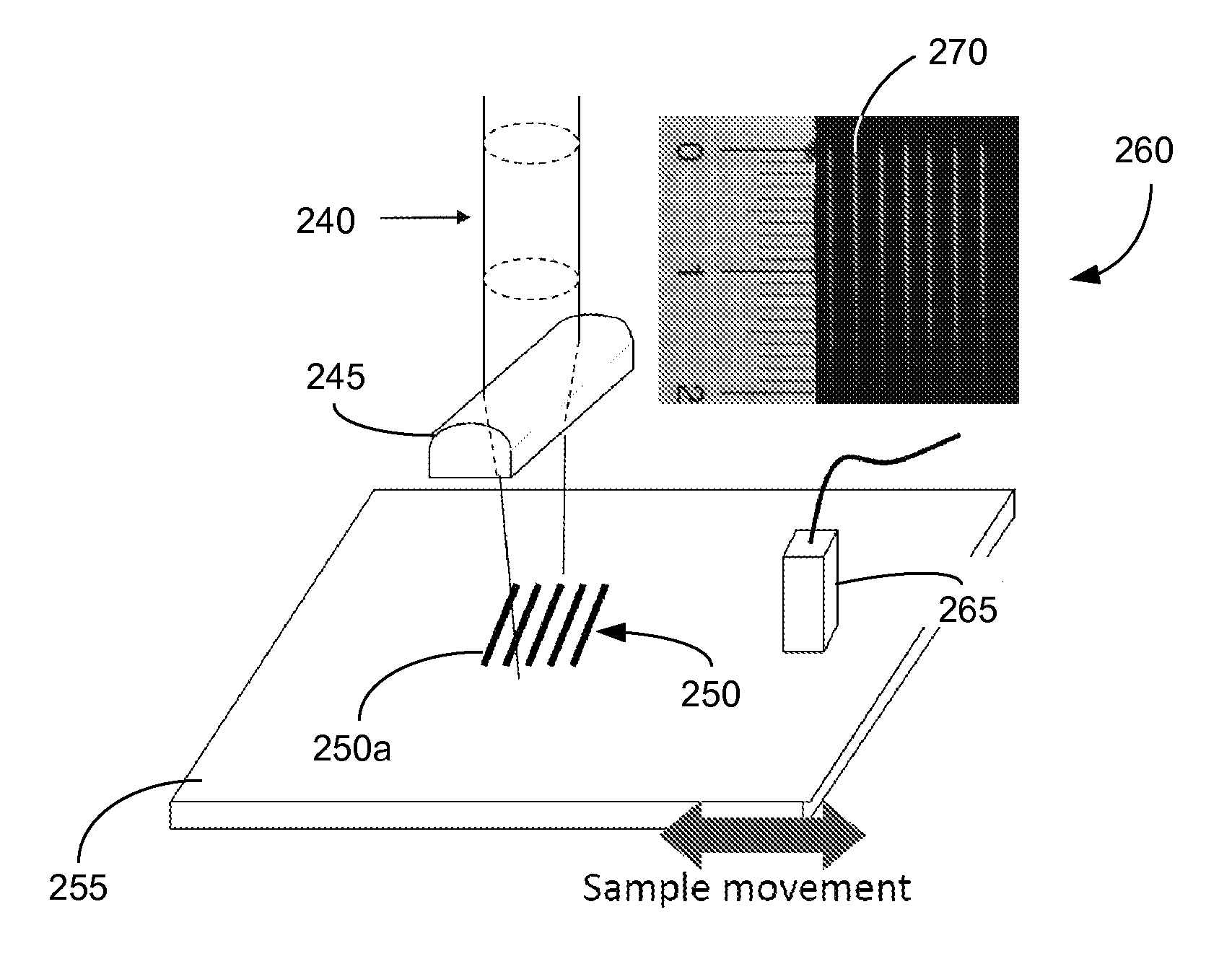
[0046]FIG. 2b shows the experiment using SLS where the laser beam 240 goes through a cylindrical lens 245 and the beam 240 is focused into a line source 250. Laser marks with 2 mm pitch are shown on laser alignment paper 260. Compared with the lines 237 in FIG. 2a, the laser e...

example 2

[0060]A set of finite element simulation on thin plates can be conducted to show that: (1) SLS has practical applications, and (2) the technique of k-ω filtering coupled with continuous wavelet transform can be used to correlate reflection coefficients to defect severity. To simplify problem at hand, the laser line sources are assumed to be infinitely long in the direction orthogonal to the plane defined by wave propagation and thickness. In this way, the problem can be reduced to a 2D plane strain problem. The material used in the simulation is aluminum with the material properties, i.e., longitudinal (CL) and shear (CT) wave speeds, listed in Table 2, below.

TABLE 2Material Properties and Wave SpeedsE (GPa)νλ (GPa)μ (GPa)CL (m / s)CT (m / s)Aluminum700.3351.126.36194.43120.0

[0061]In some embodiments, the simulation of laser generated ultrasound can be approached as a sequentially solved transient thermo-mechanical problem. The temperature field induced by the laser input can first be s...

example 3

[0068]To validate the simulation results, a set of experiments can be conducted. The experimental setup can be the same as the setup depicted in FIG. 4 and the testing procedure can be substantially the same as the procedure previously described. See, “Signal Processing Procedure” section, above. On each sample, an artificial groove is made to simulate a surface breaking defect. In the example, the plate thickness is 2 mm and the grooves are 0.8 mm wide and vary in depth. Seven depths are used in these experiments: 0.25, 0.50, 0.75, 1.00, 1.25, 1.50, and 1.75 mm (i.e., ⅛, 2 / 8, ⅜, 4 / 8, ⅝, 6 / 8 and ⅞ of the plate thickness). A set of five signals that correspond to 2 mm or 3 mm wavelength are superimposed and then processed using the signal processing procedure discussed earlier. Reflection coefficients can then be calculated and compared with simulation results. The results and comparison are shown in FIGS. 10a-10d.

Discussion of Simulation and Experimental Results

[0069]In FIGS. 9a-9d...


PUM

PropertyMeasurementUnit
traveling speedsaaaaaaaaaa
widthaaaaaaaaaa

Abstract

A system and method for providing laser generated ultrasound technique utilizing superimposed line sources is presented. The system and method can generate narrowband Lamb waves with a dominant wavelength by superimposing signals of line sources at the pitch corresponding to the desired wavelength. The superposition can be performed in software after data are collected to permit flexibility in the wavelength selected. Selecting the dominant wavelength in signals can reduce signal complexity and the speeds and frequencies of wave modes with the selected wavelength can be determined through dispersion curves. One or more additional techniques including, but not limited to, two-dimensional Fourier transforms and wavelet analysis can be used to further reduce the complexity of the signals. The system and method can be used, for example, for defect detection in thin plates.

Description

BACKGROUND OF THE INVENTION[0001]1. Field of the Invention[0002]Embodiments of the present invention relates to a system and method for generating narrowband Lamb waves for use in, for example and not limitation, non-destructive testing. Specifically, embodiments of the present invention relate to the non-contact generation of Lamb waves in thin plates using laser beams and software analysis to detect defects.[0003]2. Background of Related Art[0004]It is desirable to perform non-destructive testing (“NDT”) on a variety of materials to detect and locate, for example and not limitation, material defects, manufacturing defects, and weld quality. As a result, considerable resources have been invested to develop NDT methods such as, ultrasonic inspection, radiography, thermography, and eddy current inspection.[0005]Ultrasonic inspection techniques have gained greater acceptance for a variety of purposes in recent years. It is one of the major techniques used, for example, for inspection ...

Claims


Application Information

Patent Timeline
Patent Type & Authority Applications(United States)
IPC IPC(8): G01N29/04
CPCG01N29/2418G01N2291/0427G01N29/46
Inventor UME, IFEANYI CHARLESWU, TSUN-YEN
Owner GEORGIA TECH RES CORP
Why Eureka
Try Eureka