Normal Incidence Broadband Spectroscopic Polarimeter and Optical Measurement System
- Summary
- Abstract
- Description
- Claims
- Application Information
AI Technical Summary
Benefits of technology
Problems solved by technology
Method used
Image
Examples
first embodiment
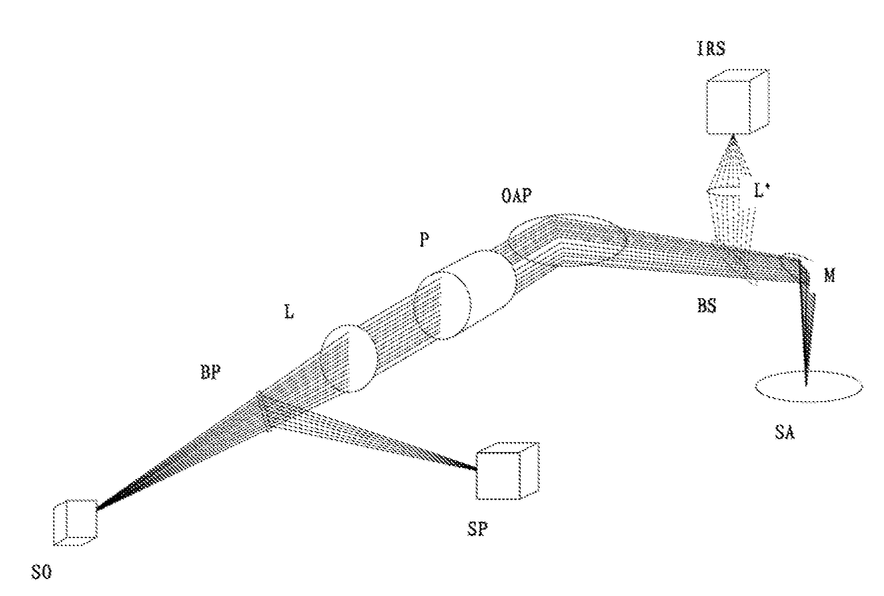
[0066]FIG. 4 shows the first embodiment of the normal incidence broadband spectroscopic polarimeter of the present invention. As shown in FIG. 4, the normal incidence broadband spectroscopic polarimeter includes a broadband point light source SO, a splitting element BP, a lens L, an off-axis parabolic mirror OAP, a polarizer P. a broadband spectrometer SP, a flat mirror M, a removable Beam-splitting Plate 135 as well as image recognition system (IRS). The image recognition system IRS includes a lens L′, an illumination light source (not shown) and CCD imaging, device (not shown). Broadband point light source SO emits broadband divergence beam, the spectrum of broadband beam is usually in the deep ultraviolet to near infrared range (from about 190 nm to 1100 nm wavelength range). in practice, broadband point light source SO can be a xenon lamp, a deuterium lamp, a tungsten lamp, a halogen lamp, a mercury lamp, a composite broadband light source including deuterium lamp and tungsten l...
second embodiment
[0075]FIG. 6 shows the second embodiment of the normal incidence broadband spectroscopic polarimeter of the present invention. Compared to the spectroscopic polarimeter shown in FIG. 4, the normal incidence broadband spectroscopic polarimeter in this embodiment doesn't contain the splitter element BP, but includes two reflector elements M2 and M3, therein the two reflector elements M2 and M3 are set between lens L and broadband. spectrometer SP respectively. For simplicity, the description of the same characteristics and structures as the first embodiment was omitted. Only the differences between these two embodiments are described.
[0076]As shown in FIG. 6, the edge of reflection element M2 is in the light path between light source SO and lens L. The reflector element M3 is placed in the optical path between the broadband spectrometer SP and reflection components M2. The beam from the light source SO propagates in the horizontal plane and then enters the lens L. Since the broadband ...
third embodiment
[0079]FIG. 7 shows the third embodiment of normal. incidence broadband spectroscopic polarimeter in the present invention. As shown in FIG. 7, the normal incidence broadband spectroscopic polarimeter includes broadband point source SO, first flat mirror M1, first off-axis parabolic mirror OAP1, second off-axis parabolic mirrors OAP2, polarizer P. broadband spectrometer SP, second fiat mirrors M2, third flat mirror M3, movable Beam-splitting Plate BS and image recognition system IRS. The image recognition system IRS includes lens L, illumination light source (not shown) and CCD imaging device (not shown). For the simplicity, the same components and functions as the first embodiment are not described in detail.
[0080]In this embodiment, the broadband point source SO emits a diverging beam with broadband spectrum which usually ranges from deep ultraviolet to near infrared (about the range from 190 nm to 1100 nm wavelength). The beam vertically propagates to the second flat mirror M2 whi...
PUM
 Abstract
Description
Claims
Application Information
 - R&D
- Intellectual Property
- Life Sciences
- Materials
- Tech Scout
- Unparalleled Data Quality
- Higher Quality Content
- 60% Fewer Hallucinations
Browse by: Latest US Patents, China's latest patents, Technical Efficacy Thesaurus, Application Domain, Technology Topic, Popular Technical Reports.
© 2025 PatSnap. All rights reserved.Legal|Privacy policy|Modern Slavery Act Transparency Statement|Sitemap|About US| Contact US: help@patsnap.com


