Precision hip replacement method

Inactive Publication Date: 2013-02-28
CRESCENT H TRUST
View PDF4 Cites 36 Cited by
  • Summary
  • Abstract
  • Description
  • Claims
  • Application Information

AI Technical Summary

Benefits of technology

[0015]To assist with proper femoral bone preparation and implantation, other embodiments may involve using a laser pointer or other positioning device to more accurately verify that the femoral broach is properly aligned with the femur while the surgeon is preparing the femu

Problems solved by technology

Studies have shown, however, that a substantially large percentage of surgeries result in cups that are not within this range.
This supports the proposition that traditional techniques have been considered by many to be unreliable for determining proper positioning of the acetabular cup or femoral component.
The so-called traditional guides, or line-of-sight, have been in use for over 40 years and are very helpful, but not as reliable as one would hope.
Unfortunately, in spite of the promise of improved results, the reluctance of patients to be exposed to a significant amount of radiation during a CT scan, the significant cost of such

Method used


Image

  • Precision hip replacement method
  • Precision hip replacement method
  • Precision hip replacement method

Examples


example 1

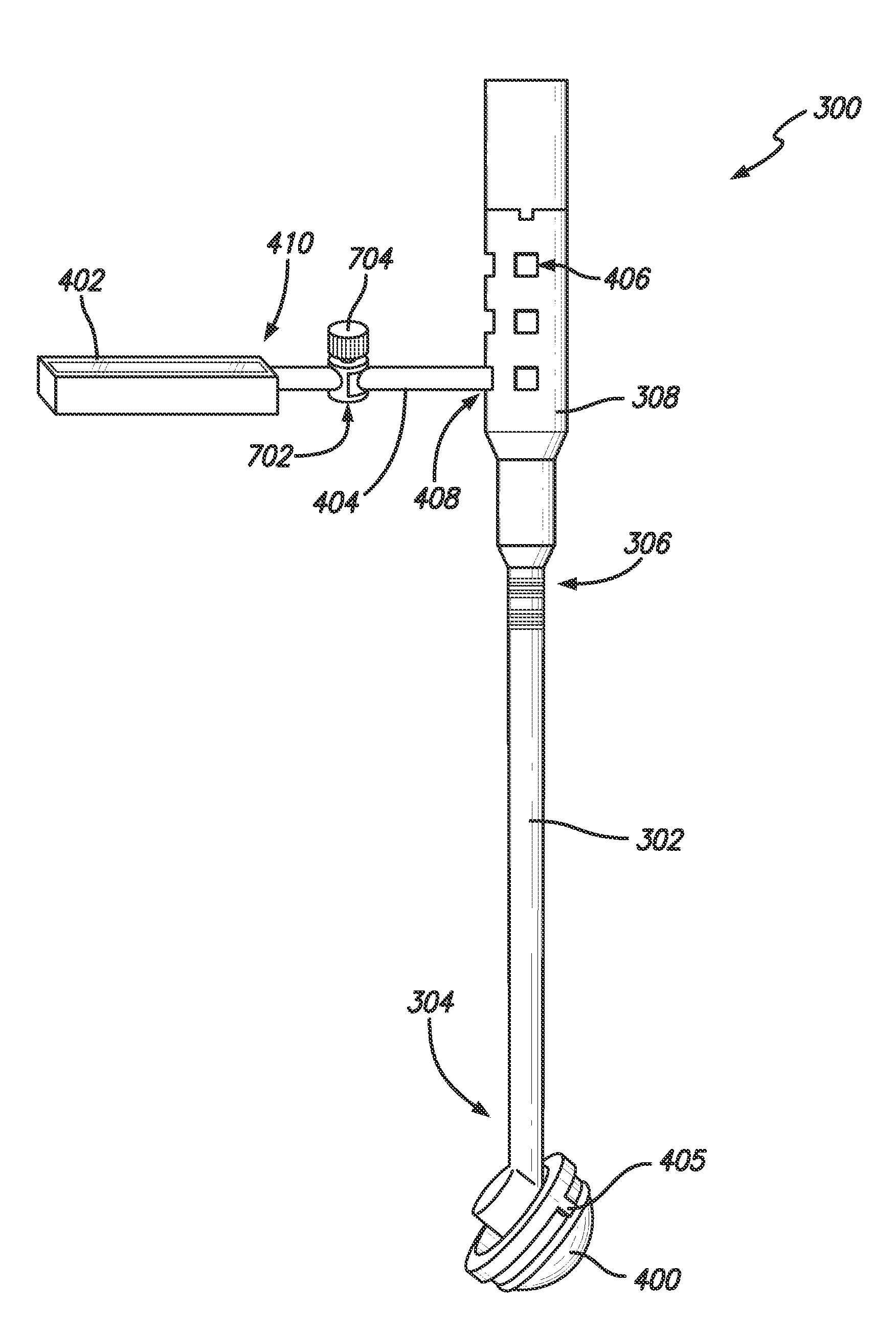
[0099]Generally, when using an acetabular component placement tool 300, start with the “Best Guess” approach (using the traditional “Sighting” Guide approach, plus the Cup Holder / Alignment Guide), obtain a radiographic or fluoroscopic image, and then use one embodiment of the present invention to make precise adjustments.

[0100]For example, once all of the proper incisions have been made and the acetabular components 400 is initially put in place with an acetabular component placement tool 300, the present settings of abduction and anteversion are read from the gyroscopic device 402. An imaging device 804, such as those used in radiographic or fluoroscopic imaging, can be used to create a radiographic or fluoroscopic image. For example, the imaging device 804 may be an x-ray machine emitting x-rays 806. From the radiographic imaging, the degree of abduction and anteversion needed for proper placement of the acetabular component 400 can be determined. Then, as the acetabular component...

example 2

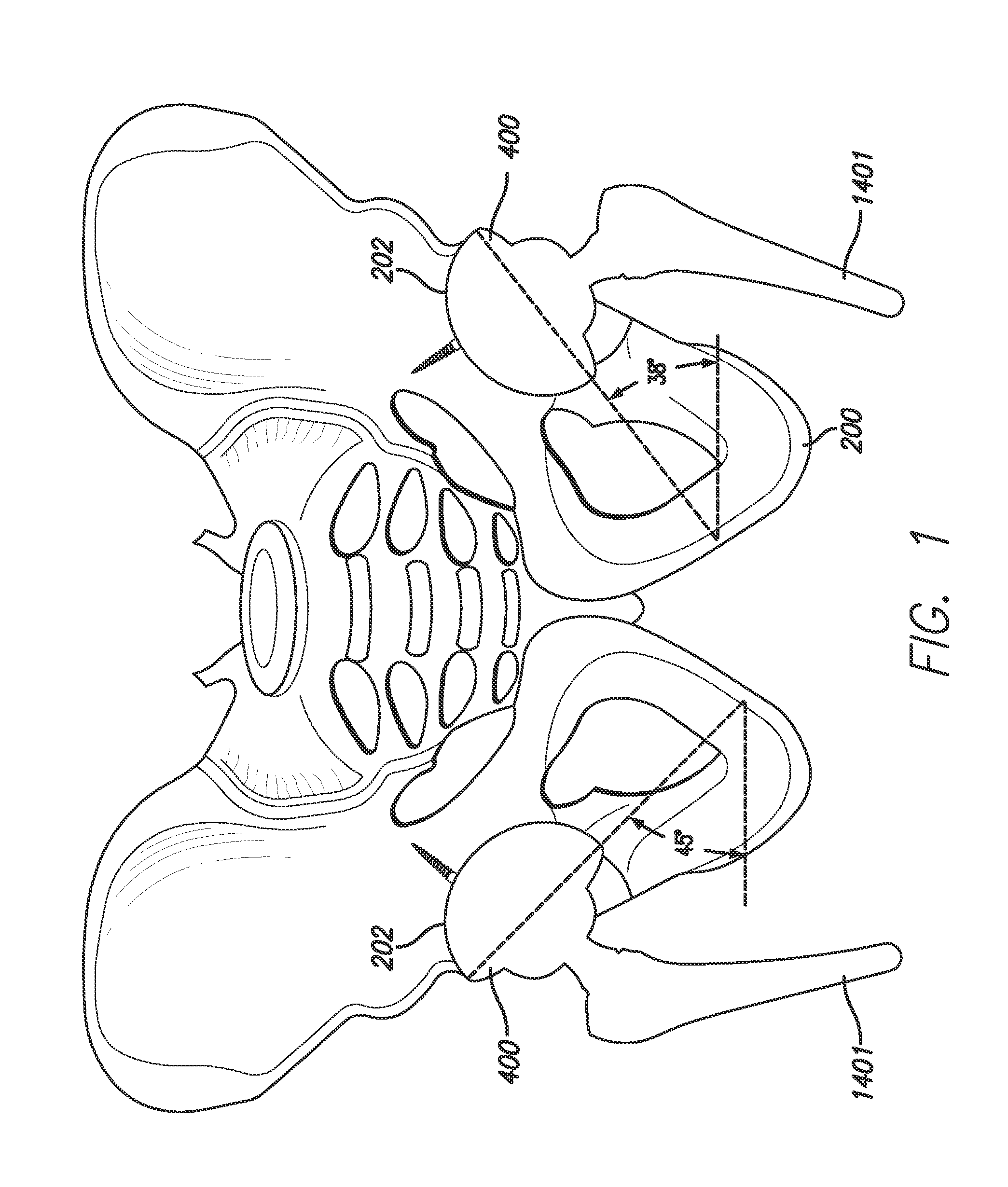
[0102]In yet another embodiment, the best guess position can be made more precise by applying the present invention to the standard cup holder / alignment guide and, rather than relying on line of sight, i.e., identifying a neutral or zeroing orientation that at present is simply “sighted” in relation to operating room structures (a corner of the room, a vertical line of tiles on the wall, or any nearby straight vertical object) or imprecise anatomical landmarks (patient's trunk, shoulder, opposite kidney). That is to say, that the gyroscopic indicator is capable of indicating true vertical for the upright part of the guide and true zero or neutral for anteversion. After cup placement in the orientation directed by the combined references of the present invention connected (physically or remotely) to the recently redesigned alignment guide, the guide is then removed. Screws or a trial liner may then be placed. A femoral trial may also be placed in the best guess position either before...

example 3

[0104]This example is similar to Example 1 above, but including an attached “gyrometer.” The reamer basket (not shown) itself can act as a surrogate for the acetabular component 400. The gyrometer 402 settings can then be noted, an x-ray taken, and any corrections identified by measuring angles on the x-ray. This could be considered a way of calibrating the gyrometer 402. When returned to the same position (as indicated by the subsequent gyrometer 402 readout), correct acetabular component 400 positioning is then achieved by placing the acetabular component 400 in position, which results in corrected gyrometer readings.

[0105]By using a digital gyroscopic unit, the surgeon can quantify the orientation in space of the acetabular component greatly improving on the “best guess” orientation in which the surgeon might otherwise eyeball the positioning. Clinical research to date (including, Rubash, et al.) confirms a 40% error rate with current “best guess” in which the surgeon does not us...


PUM


Abstract

A method for accurately positioning the acetabular cup in a minimally invasive total hip arthroplasty (THA), comprising the steps of (a) placing the cup in roughly the correct position in the acetabulum using a acetabular component placement tool, (b) taking a first abduction reading and a first anteversion reading using a gyroscopic positioning unit aligned with the acetabular component placement tool, (c) taking an image of at least a portion of the cup using a radiography unit, (d) using the image to determine the actual orientation of the cup and required position of the cup to properly orient the acetabular component, (e) incrementally altering the position of the cup by using a striking tool, (f) taking new abduction and anteversion readings using the gyroscopic unit to determine the relative movement of the cup caused by the tapping, and (g) repeating any of the steps as necessary.

Description

CROSS-REFERENCES TO RELATED APPLICATIONS[0001]This patent application claims the benefit of U.S. Provisional Application No. 61 / 528,744, filed Aug. 29, 2011, and U.S. Provisional Patent Application No. 61 / 567,869, filed Dec. 7, 2011. All applications are incorporated herein by this reference thereto.BACKGROUND OF THE INVENTION[0002]1. Field of the Invention[0003]This invention relates to the field of minimally invasive surgical techniques for a joint replacement, and more particularly, methods for accurately positioning components for hip or knee joint replacement procedures.[0004]2. Description of the Related Art[0005]During the course of total hip arthroplasty, acetabular and femoral prostheses are placed. In order for the implants to function up to their capacity, generally meaning greater than twenty (20) years of clinical reliability, each component must be placed in a specific position in relation to the patient's native anatomy. Specifically, proper positioning of the acetabu...

Claims


Application Information

Patent Timeline
IPC IPC(8): A61B17/56
CPCA61B17/164A61B17/1659A61B17/1668A61F2/4609A61B17/1746A61B17/175A61B17/1703A61B2090/067A61B2034/2048A61B17/320016A61B17/32093A61B2017/320044A61B17/3494
Inventor PENENBERG, BRAD L.
Owner CRESCENT H TRUST
Why Eureka
Try Eureka