Laser spot control in maldi mass spectrometers

a mass spectrometer and laser spot technology, applied in mass spectrometers, separation processes, instruments, etc., can solve the problems of high noise, small laser spot size, and very fine laser spots of only a few micrometers in diameter, and achieve optimal utilization of all analyte molecules, rapid position control, and high degree of utilization of analyte molecules

Active Publication Date: 2013-03-07
BRUKER DALTONIK GMBH & CO KG
View PDF13 Cites 30 Cited by
  • Summary
  • Abstract
  • Description
  • Claims
  • Application Information

AI Technical Summary

Benefits of technology

[0013]The rapid positional control allows optimal utilization of all the analyte molecules from a specified area of a sample (the “sample site”) by uniform ablation of the sample within this area with a single laser spot, or preferably with a laser spot pattern, without having to move the sample support plate in order to produce the spatially shifted pattern for the ablation. The uniform ablation of samples on the slowly moving sample support plate may be obtained by controlling the laser spot to ablate the sample in a narrow raster of points, point after point. If a laser spot pattern is used for this uniform ablation, the spot pattern and the raster pattern may overlap each other.
[0014]In order to acquire mass spectra of different sample sites sequentially, the positional control for the laser spot allows the sample support to be moved continuously, preferably at a uniform speed in one direction while, by moving the laser beam, the spot position is made to follow in such a way that individual single shot time-of-flight spectra are obtained from the same sample site for each mass spectrum. Therefore, in this phase, the relative movements between sample support plate and laser spot have the value zero. The small laser spot movements for uniform ablation of a specified area of the sample site can also be superimposed onto this “following movement”. For imaging mass spectrometry, the spatial resolution for the individual mass spectra can be retained, and simultaneously a high degree of utilization for the analyte molecules is achieved. For a subsequent acquisition of a mass spectrum at a different sample site, the spot position is moved to the new sample site by means of a rapid movement of the mirror within a period of only 100 microseconds until the next laser shot. In this phase, the relative movements between sample support plate and laser spot are very different. This mode of operation does, however, require ion-optical corrections to the changing beam path of the ions through the mass spectrometer and corrections to the changed flight times to be made. The sample sites on the sample support plate do not need to be in a one-dimensional row; sample sites which are side by side can also be analyzed by lateral movements of the laser spot. It is thus possible to analyze samples on a number of tracks while the sample support plate is moved uniformly in one direction.
[0017]The fast positional control for the laser spots can also be used to solve further problems. It is, for example, possible to achieve fully automatic adjustment of MALDI time-of-flight mass spectrometers with special samples which supply spectra with constant intensity over a sufficiently long period, controlled by programs in the connected computer. This not only makes it possible to automatically determine the best spot position relative to the ion optics of the spectrometer and all necessary correction voltages for the ions from spots outside of this optimum position; it is also possible to optimally adjust elements of the ion optics themselves, at least if these ion-optical elements, such as the reflector and detector, are equipped with movement devices, at least for the time of an adjustment. However, the positioning of elements of the laser system, like the beam focusing optical lens system, can be optimized too, if these are equipped with movement devices.

Problems solved by technology

There is, however, a problem regarding the production of very fine laser spots of only a few micrometers in diameter.
All mirrors show a statistical noise of their movement; the smaller the mirrors, the higher the noise.

Method used


Image

  • Laser spot control in maldi mass spectrometers
  • Laser spot control in maldi mass spectrometers
  • Laser spot control in maldi mass spectrometers

Examples


Embodiment Construction

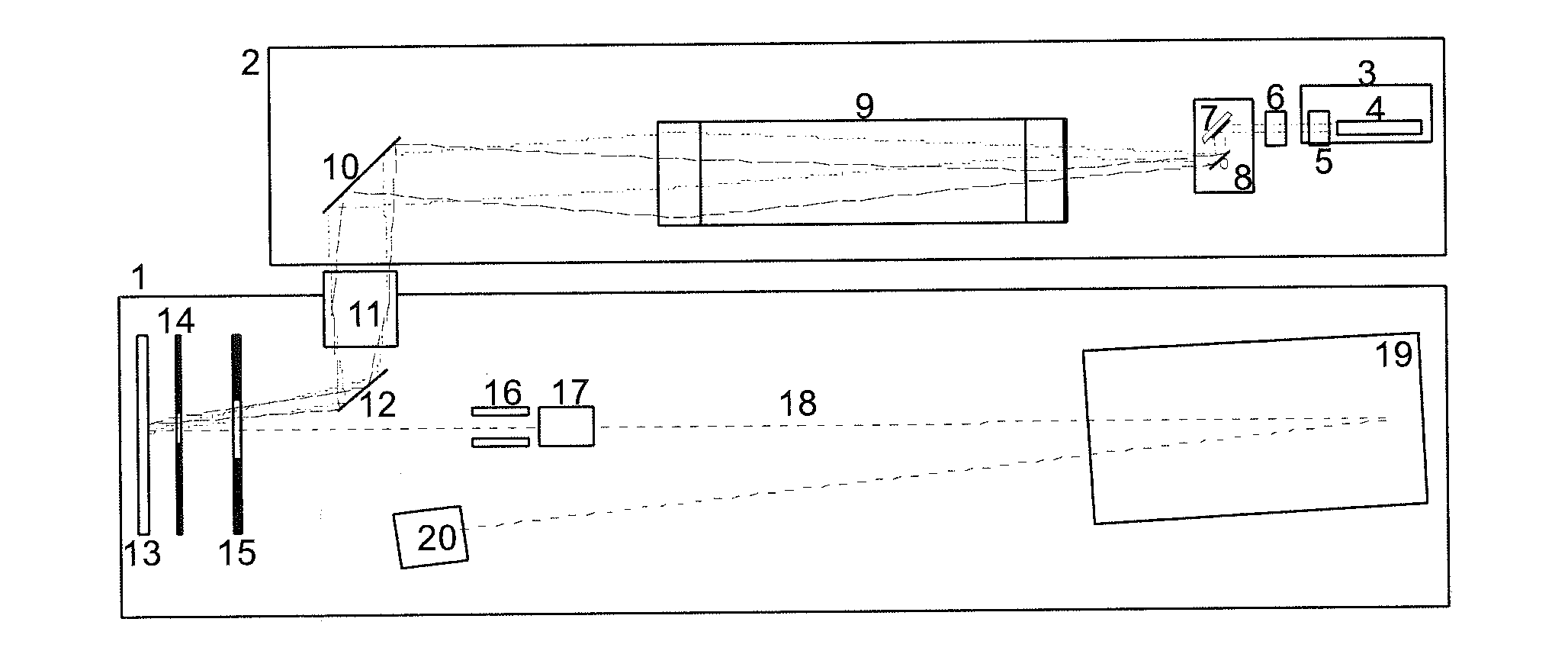
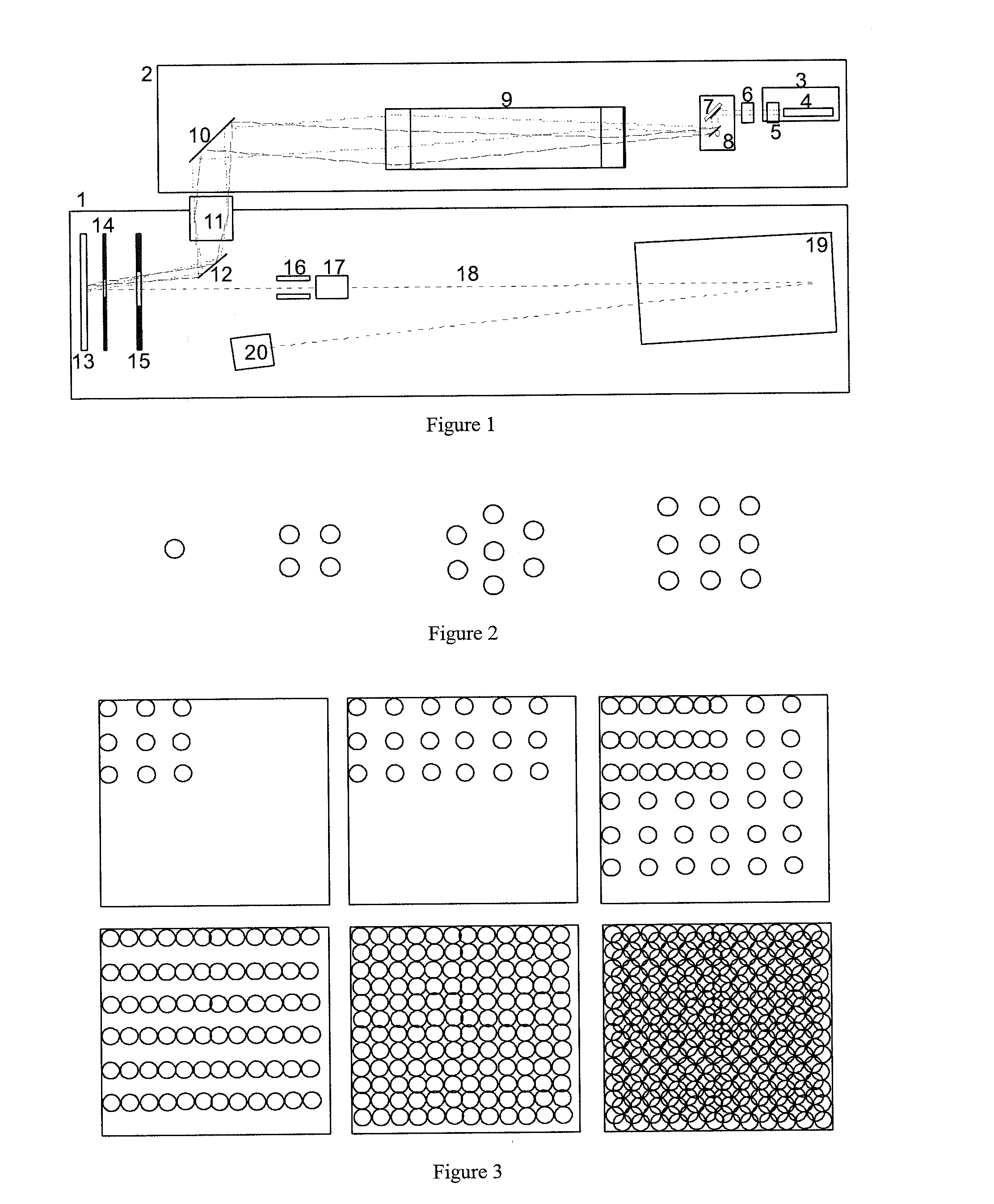
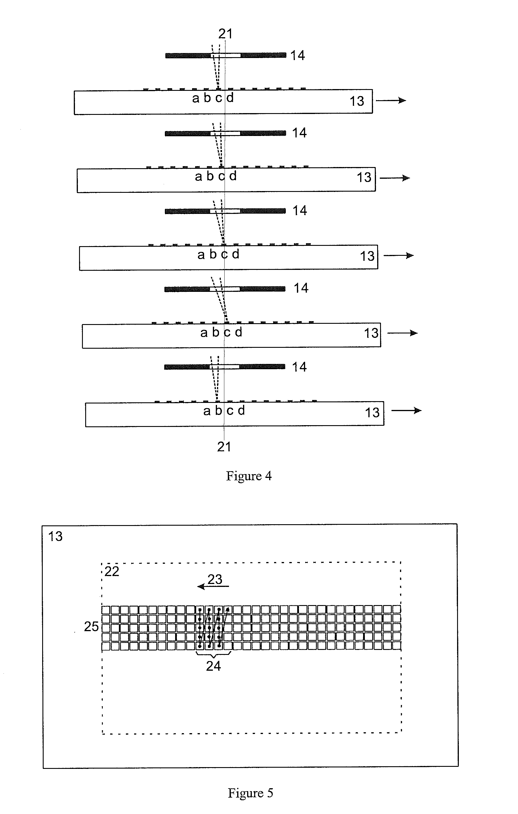
[0024]As has already been explained above, an objective of the invention is to avoid intermittent movements or fast to-and-fro movements of the mechanically inert sample support plate, including its holder, as far as possible, and to replace it with a low-inertia movement device for the laser light beam. The movement device should be capable of moving the laser spot to a different site in a time of only 100 microseconds, i.e. between two laser shots (of a laser system with a repetition rate of 10 kHz). A laser system with a repetition rate of 2 kHz requires a time of half a millisecond. In princi-ple, different types of deflection system can be used for the fast positional control of the laser spot or laser spot pattern, such as piezo-electrically moved mirrors or crystals with electrically changeable refraction. However, electrically moved galvo mirrors, as have been developed for laser scanners or laser labeling equipment, are technically most mature and particularly low-cost. At ...


PUM


Abstract

Mass spectrometers ionize samples by matrix-assisted laser desorption (MALDI). The samples are located on a moveable support plate, and irradiated by a pulsed laser. A fast positional control of laser spots is provided via a system of rotatable mirrors to relieve strain on a support plate motion drive. If the spot position is finely adjusted by the mirror system and follows the movement of the sample support plate, the intermittent movement of the sample support can be replaced with a continuous uniform motion. The fast positional control allows more uniform ablation of a sample area. Galvo mirrors with low inertia may be used between the beam generation and a Kepler telescope in the housing of the laser. The positional control can also provide a fully automatic adjustment of MALDI time-of-flight mass spectrometers, at least if the ion-optical elements are equipped with movement devices.

Description

PRIORITY INFORMATION[0001]This patent application claims priority from Getman Patent Application No. 10 2011 112 649.3 filed on Sep. 6, 2011, which is hereby incorporated by reference in its entirety.FIELD OF THE INVENTION[0002]The invention relates to mass spectrometers with ionization of samples by matrix-assisted laser desorption (MALDI), wherein the samples located on a moveable support plate are irradiated by a pulsed laser.[0003]The invention provides a fast positional control of laser spots via a system of rotatable mirrors to assist the support plate motion drive, which by its high inertia is not able to follow a fast movement from sample to sample during a fast sequence of analyses. If the laser spot position is, in a micro-scale, controlled by the mirror system and follows the motion of the sample support plate, at least in phases, the stepwise movement of the sample support can be replaced by a continuous movement, preferably at uniform speed. Furthermore, the fast positi...

Claims


Application Information

Patent Timeline
Patent Type & Authority Applications(United States)
IPC IPC(8): H01J49/40G02B23/14
CPCH01J49/0004H01J49/164
Inventor HOLLE, ARMINHAASE, ANDREASHOEHNDORF, JENS
Owner BRUKER DALTONIK GMBH & CO KG
Why Eureka
Try Eureka