
Multiport Vehicle DC Charging System with Variable Power Distribution

a charging system and multi-vehicle technology, applied in the direction of charging stations, battery/fuel cell control arrangements, transportation and packaging, etc., can solve the problems of limited current charging infrastructure, relatively inefficient and costly approach

Active Publication Date: 2013-03-07
TESLA INC
View PDF2 Cites 99 Cited by
  • Summary
  • Abstract
  • Description
  • Claims
  • Application Information

AI Technical Summary

Benefits of technology

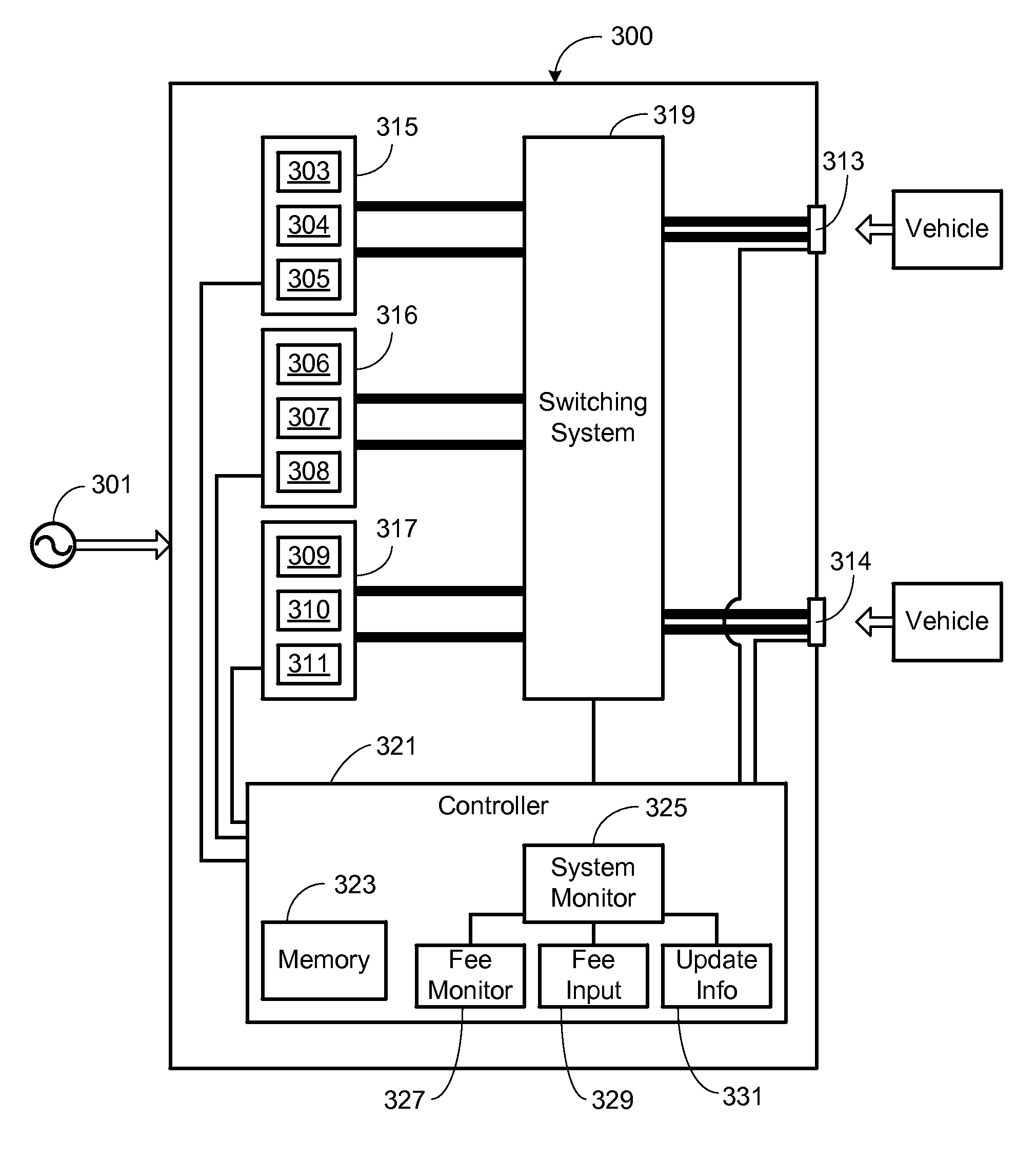
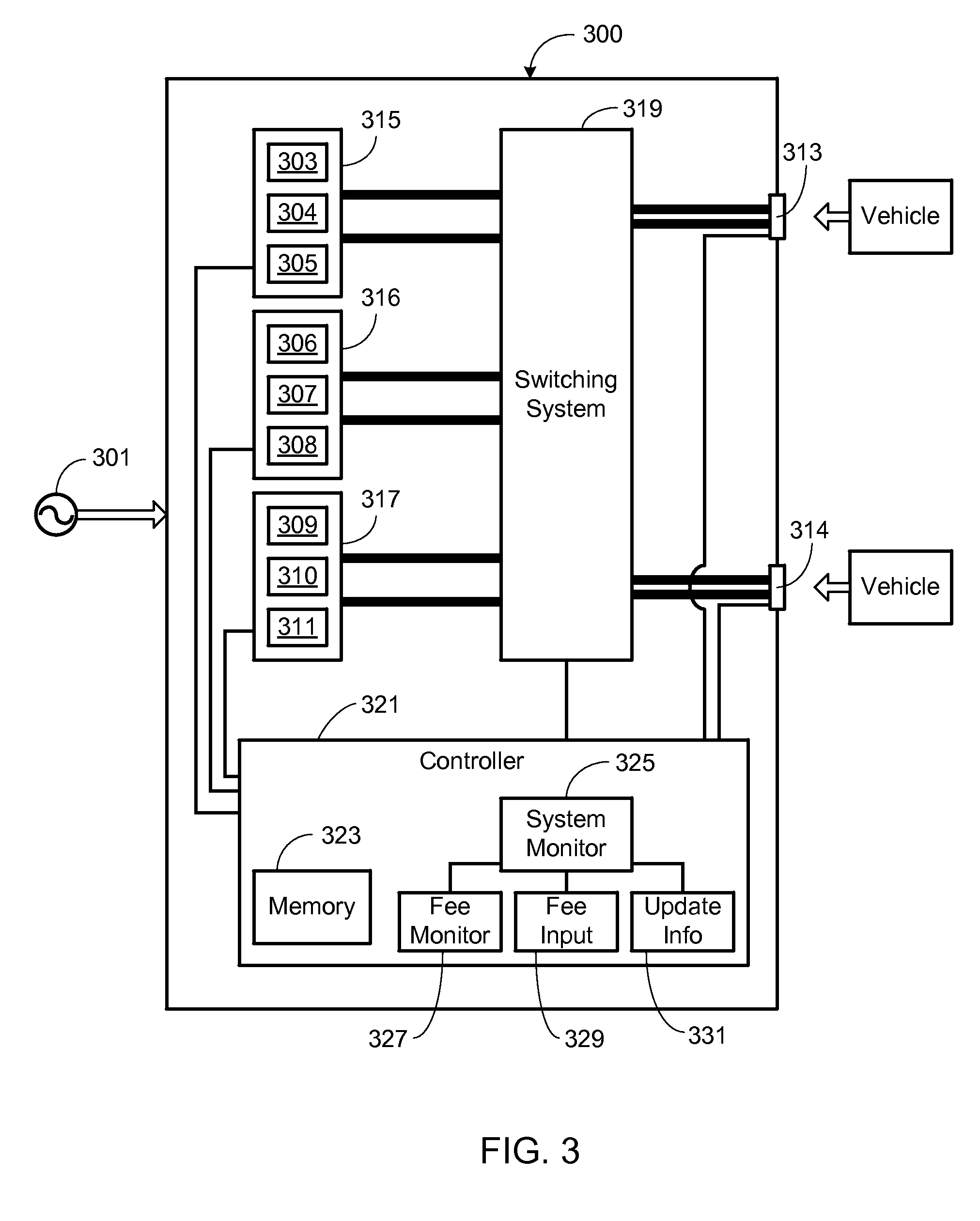
The present invention is a battery charging station that includes multiple charge ports and power stages with AC to DC converters to provide the maximum available charging power. A switching system is used to connect the power stages to the charging ports, and a system monitor determines the current conditions of the charging station and ports. A controller controls the switching system based on predefined power distribution rules and current conditions. The charging station can prioritize power distribution based on factors like vehicle arrival time, charger usage fees, vehicle priority, customer priority, battery pack SOC, and intended departure time. The charging station can also accept charging port reservations and display charging port reservation information. The technical effects of the invention include efficient and safe battery charging, improved user experience, and optimized power distribution.

Problems solved by technology

The use of such vehicles, more specifically the use of vehicles which rely on fossil fuels, e.g., gasoline, creates two problems.
First, due to the finite size and limited regional availability of such fuels, major price fluctuations and a generally upward pricing trend in the cost of gasoline are common, both of which can have a dramatic impact at the consumer level.
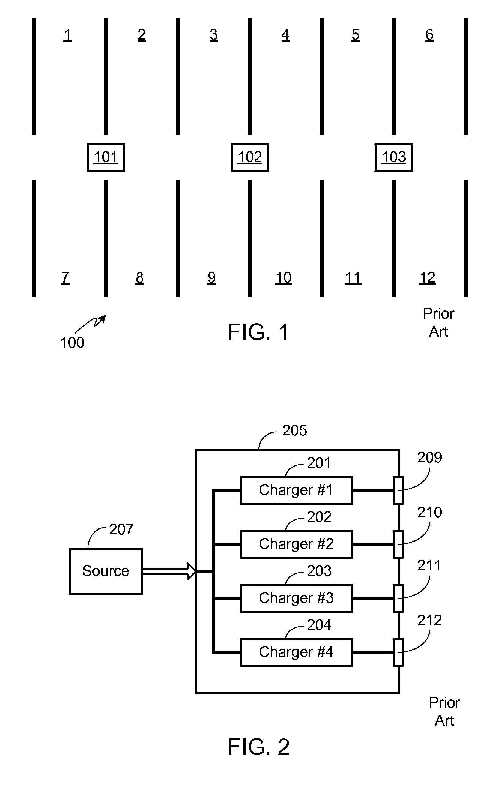
Unfortunately, the current charging infrastructure is quite limited.
While this approach may be used to significantly improve vehicle access to a charging source, it is a relatively inefficient and costly approach due to the duplication of charging circuits 201-204.

Method used


Image

  • Multiport Vehicle DC Charging System with Variable Power Distribution
  • Multiport Vehicle DC Charging System with Variable Power Distribution
  • Multiport Vehicle DC Charging System with Variable Power Distribution

Examples


Embodiment Construction

[0022]In the following text, the terms “battery”, “cell”, and “battery cell” may be used interchangeably and may refer to any of a variety of different cell types, chemistries and configurations including, but not limited to, lithium ion (e.g., lithium iron phosphate, lithium cobalt oxide, other lithium metal oxides, etc.), lithium ion polymer, nickel metal hydride, nickel cadmium, nickel hydrogen, nickel zinc, silver zinc, or other battery type / configuration. The term “battery pack” as used herein refers to multiple individual batteries, typically contained within a single piece or multi-piece housing, the individual batteries electrically interconnected to achieve the desired voltage and capacity for a particular application. The terms “battery” and “battery system” may be used interchangeably and as used herein refer to an electrical energy storage system that has the capability to be charged and discharged such as a battery, battery pack, capacitor or supercapacitor. The term “e...


PUM


Abstract

A battery charging station is provided that includes a plurality of charge ports, a plurality of power stages where each power stage includes an AC to DC converter and where each power stage provides a portion of the charging station's maximum available charging power, a switching system that is used to couple the output of the power stages to the charging ports, a system monitor that determines current charging station and vehicle conditions, and a controller that controls operation of the switching system in accordance with a predefined set of power distribution rules and on the basis of the current charging station and vehicle conditions. Current charging station and vehicle conditions may include vehicle arrival time, usage fees, vehicle and / or customer priority information, battery pack SOC, and / or intended departure time.

Description

FIELD OF THE INVENTION[0001]The present invention relates generally to battery charging systems and, more particularly, to a method and apparatus for distributing electrical power to recharge one or more electric and hybrid vehicles from a single source.BACKGROUND OF THE INVENTION[0002]A large percentage of the world's vehicles run on gasoline using an internal combustion engine. The use of such vehicles, more specifically the use of vehicles which rely on fossil fuels, e.g., gasoline, creates two problems. First, due to the finite size and limited regional availability of such fuels, major price fluctuations and a generally upward pricing trend in the cost of gasoline are common, both of which can have a dramatic impact at the consumer level. Second, fossil fuel combustion is one of the primary sources of carbon dioxide, a greenhouse gas, and thus one of the leading contributors to global warming. Accordingly, considerable effort has been spent on finding alternative drive systems ...

Claims


Application Information

Patent Timeline
IPC IPC(8): H02J7/00
CPCH02J7/00B60L2250/14B60L1/003B60L11/1816B60L11/1824B60L11/184B60L11/1844B60L11/1846B60L11/1848B60L11/185B60L11/1861B60L2200/42B60L2230/16B60L2240/34B60L2240/545B60L2240/80Y02T10/7005H02J7/0027B60L53/11B60L53/14B60L53/64B60L58/12B60L53/665B60L53/30B60L53/63B60L53/65H02J7/02Y02T90/14Y04S10/126Y04S30/14B60L53/305H02J2310/48Y02E60/00Y02T10/70Y02T10/7072Y02T90/12Y02T90/167Y02T90/16H02J7/0013H02J7/0042
Inventor NERGAARD, TROY ADAMSUKUP, MARTINDONHOWE, KRISTOFFER JOHNVAN DYKE, CHRISTOPHER HUGOWONG, WARWICK KA KUI
Owner TESLA INC
Learn More