Calibration of active antenna arrays for mobile telecommunications

Active Publication Date: 2013-03-07
ALCATEL LUCENT SAS
View PDF6 Cites 70 Cited by
  • Summary
  • Abstract
  • Description
  • Claims
  • Application Information

AI Technical Summary

Benefits of technology

[0015]The standing wave signal may be sampled at predetermined tapping or coupling points along the length of the line, which all have the same amplitude and phase relationships, or at least a known relationship of phase and amplitude. As preferred, such coupling points occur at or adjacent voltage maxima/minima within the standing wave, where the change of voltage with respect to line length is very small. Hence, the requirement for mechanical accuracy in positioning o

Problems solved by technology

This method usually requires (depending on the size of the array and accuracy) very complex algorithms to mutually adjust the elements, because the adjustment relies on mutual coupling of the elements, which is weak for elements at larger distances.
Or a factory-calibration is used, which is complicated to recalibrate if, e.g. during the operation of the array, any phase or amplitude changes in the RF-signal-generation and transmission occurs.
The additional receiver and transmitter increase cost and the associated algorithms require extra computational resources.
This method suffers from three draw backs:
a) Each transmission line has to be of at least half the length of the array size. That means even if an element is located very close to the reference signal generator, it requires a long cable. This increases cost unnecessarily and the volume and weight of the network.
b) The number of transceiver elements is limited to the preset number of sig

Method used


Image

  • Calibration of active antenna arrays for mobile telecommunications
  • Calibration of active antenna arrays for mobile telecommunications
  • Calibration of active antenna arrays for mobile telecommunications

Examples


Embodiment Construction

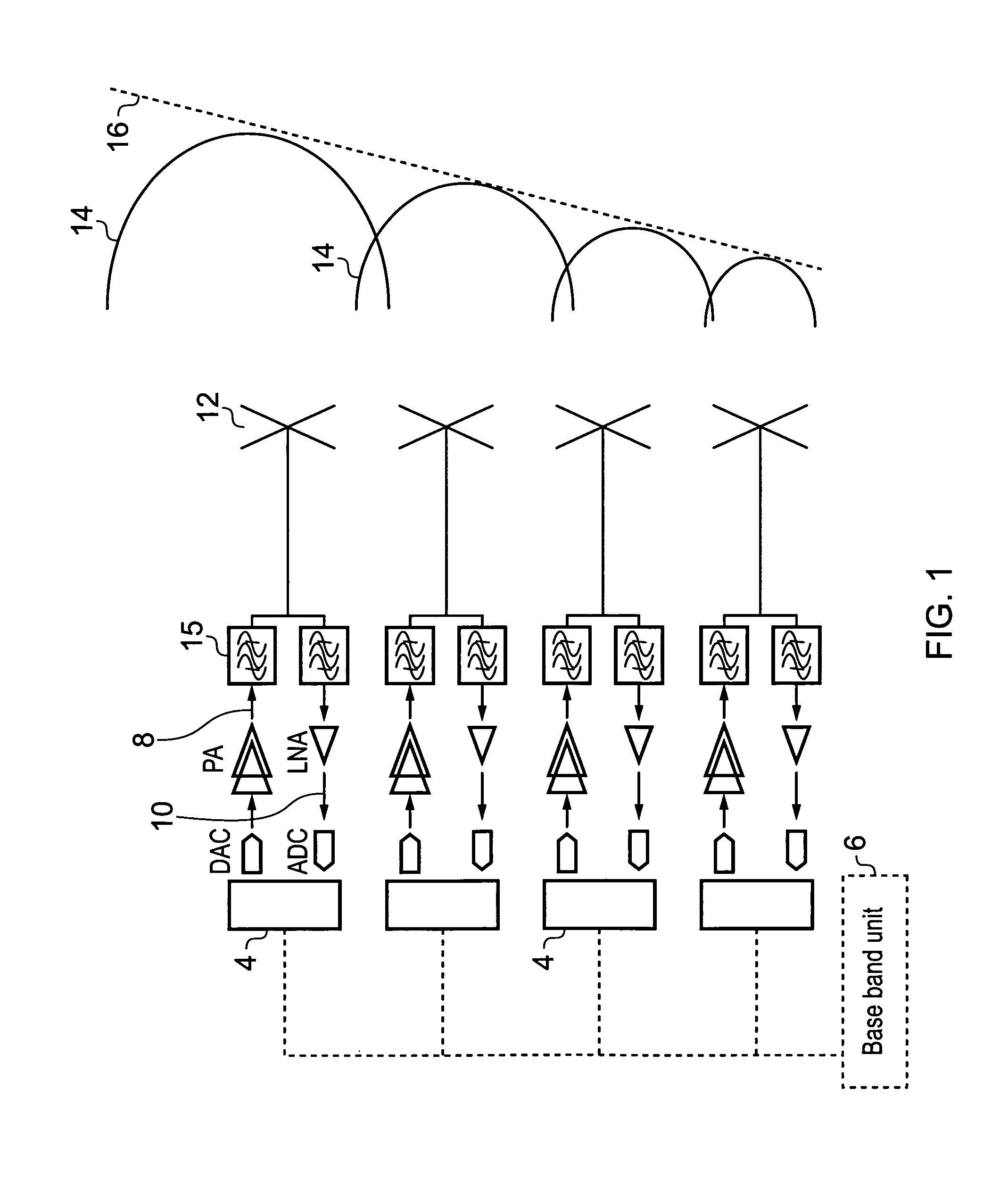
[0028]In the following description, where reference is made to the transmit path, it will be appreciated the invention can be used in the same way to provide a reference for the receive path. The invention is applicable both to transmit and receive cases.

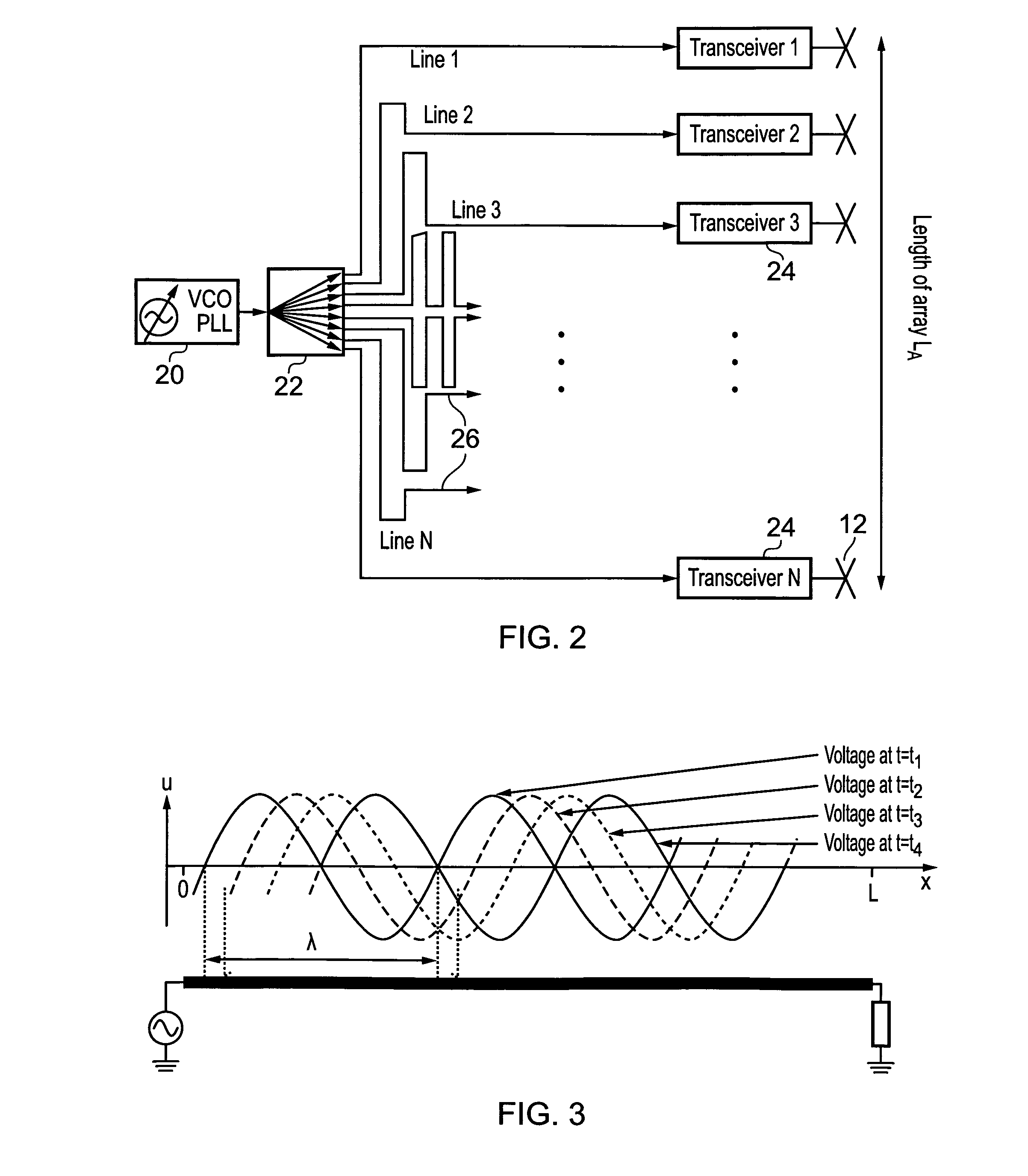
[0029]Referring to FIG. 2, this shows a means of distributing a reference signal of phase and amplitude to the individual transceivers of an active antenna array. A centrally generated reference signal 20 (VCO PLL) is split in an N-way-power divider 22 (1:N-splitter) and connected to the reference input of each transceiver unit 24 by respective transmission lines 26 of equal length I. Length I is nominally equal to half the length of the array IA. This forms the known star-distribution network, and any change of the line length results in a change of the phase length, giving rise to the disadvantages noted above. This is due to the travelling nature of the wave propagation on the line: the phase change Δφ is proportional to the leng...


PUM


Abstract

In order to calibrate in amplitude and phase the individual transceiver elements (4) of an active antenna array for a mobile telecommunications network, each transceiver element including a transmit and a receive path (8, 10) coupled to an antenna element (12), each transceiver element includes a comparator (100) for comparing phase and amplitude of transmitted or received signals with reference signals in order to adjust the characteristics of the antenna beam. In order to provide an accurate means of reference signal distribution, a feed arrangement distributes the reference signals and includes a waveguide (50) of a predetermined length which is terminated at one end (52) in order to set up a standing wave system along its length, and a plurality of coupling points (56) at predetermined points along the length of the waveguide, which are each coupled to a comparator of a respective transceiver element.

Description

FIELD OF THE INVENTION[0001]The present invention relates to antenna arrays employed in mobile telecommunications systems, and in particular to the phase and / or amplitude calibration of RF signals in active antenna arrays.BACKGROUND ART[0002]In wireless mobile communications, active, or phased array, antenna systems are emerging in the market, which are used for beam steering and beam forming applications. Active antenna systems allow increase of network capacity, without increasing the number of cell sites, and are therefore of high economical interest. Such systems comprise a number of individual antenna elements, wherein each individual antenna element transmits RF energy, but adjusted in phase relative to the other elements, so as to create a beam pointing in a desired direction. It is essential for the functionality of the system to be able to measure, control and adjust the phase coherency of the signal being radiated from the various individual antenna elements of the antenna...

Claims


Application Information

Patent Timeline
IPC IPC(8): H01Q21/00
CPCH01Q3/267H01Q3/26H01Q21/08
Inventor PIVIT, FLORIANHESSELBARTH, JAN
Owner ALCATEL LUCENT SAS
Why Eureka
Try Eureka