Eureka AIR delivers breakthrough ideas for toughest innovation challenges, trusted by R&D personnel around the world.

Combustion apparatus

Inactive Publication Date: 2013-03-14
NORITZ CORP
View PDF7 Cites 4 Cited by
  • Summary
  • Abstract
  • Description
  • Claims
  • Application Information

AI Technical Summary

Benefits of technology

The present invention is a combustion apparatus that prevents the scattering of drain water from the exhaust port and reduces noise levels during operation. It achieves this by ensuring that the interspace is in fluid communication with the exhaust channel through an upper surface opening and a communication opening in the bottom of the heat exchange chamber. Additionally, the water droplet baffle plate is positioned at an angle to facilitate the separation of water droplets from the plate. This prevents the adhesion of water droplets to the plate and ensures that the combustion exhaust flow is collided against the plate, resulting in the separation of water droplets. These technical effects contribute to the quietness of operation and improve the performance of the combustion apparatus.

Problems solved by technology

Incidentally, the condensing-type combustion apparatus requires space necessary for the arrangement of the latent heat exchanger.
This may cause inconveniences, such as a lack of space for placing a sound absorption material for the purpose of noise control, a complexity of the route through which the combustion exhaust passes and other troublesome conditions.
Therefore, it is quite likely that the generation of noise associated with combustion and the generation of noise associated with the passage of combustion exhaust will take place.

Method used


Image

  • Combustion apparatus
  • Combustion apparatus
  • Combustion apparatus

Examples


Embodiment Construction

[0019]Hereinafter, embodiments of the present invention will be described with reference to the drawing figures.

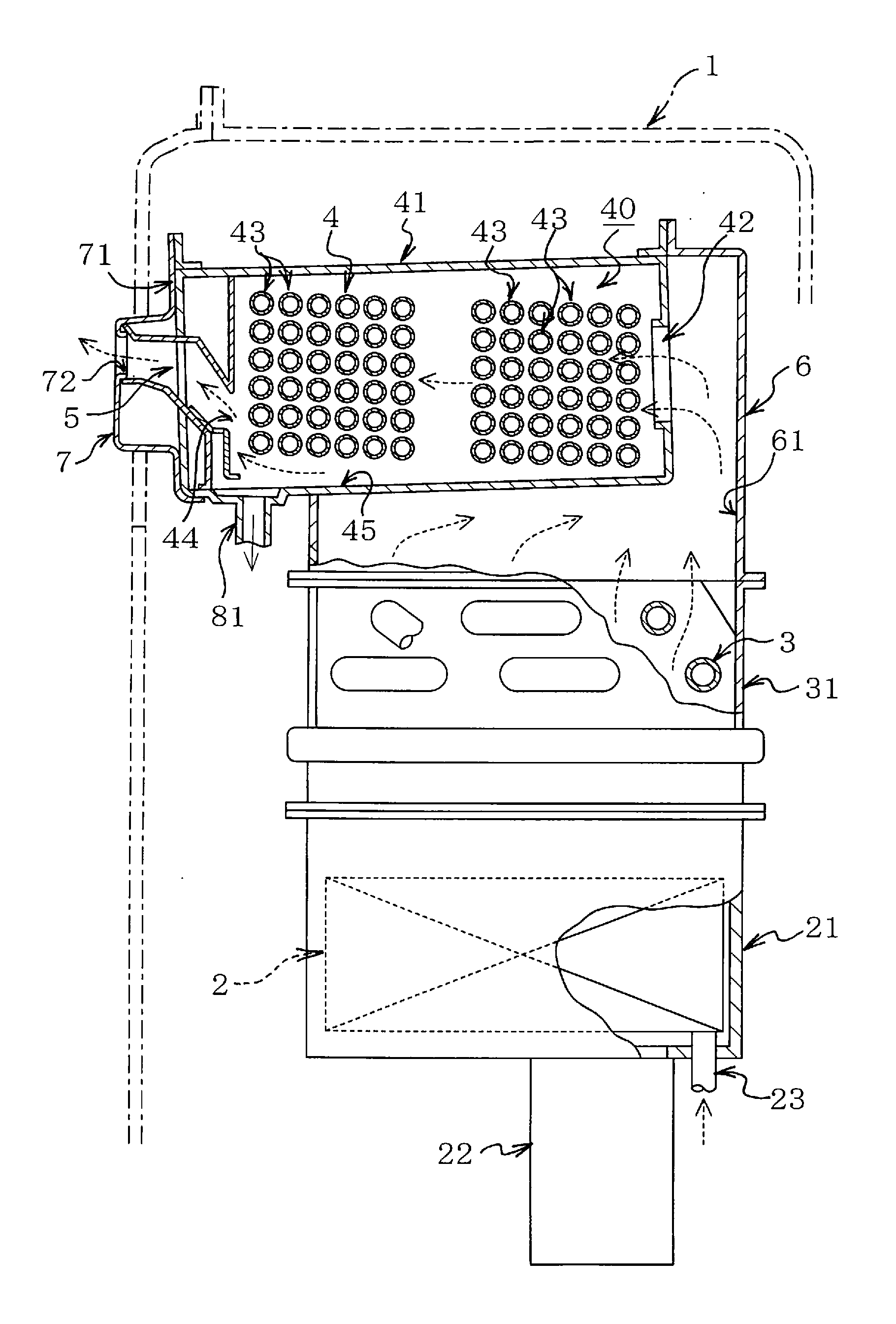
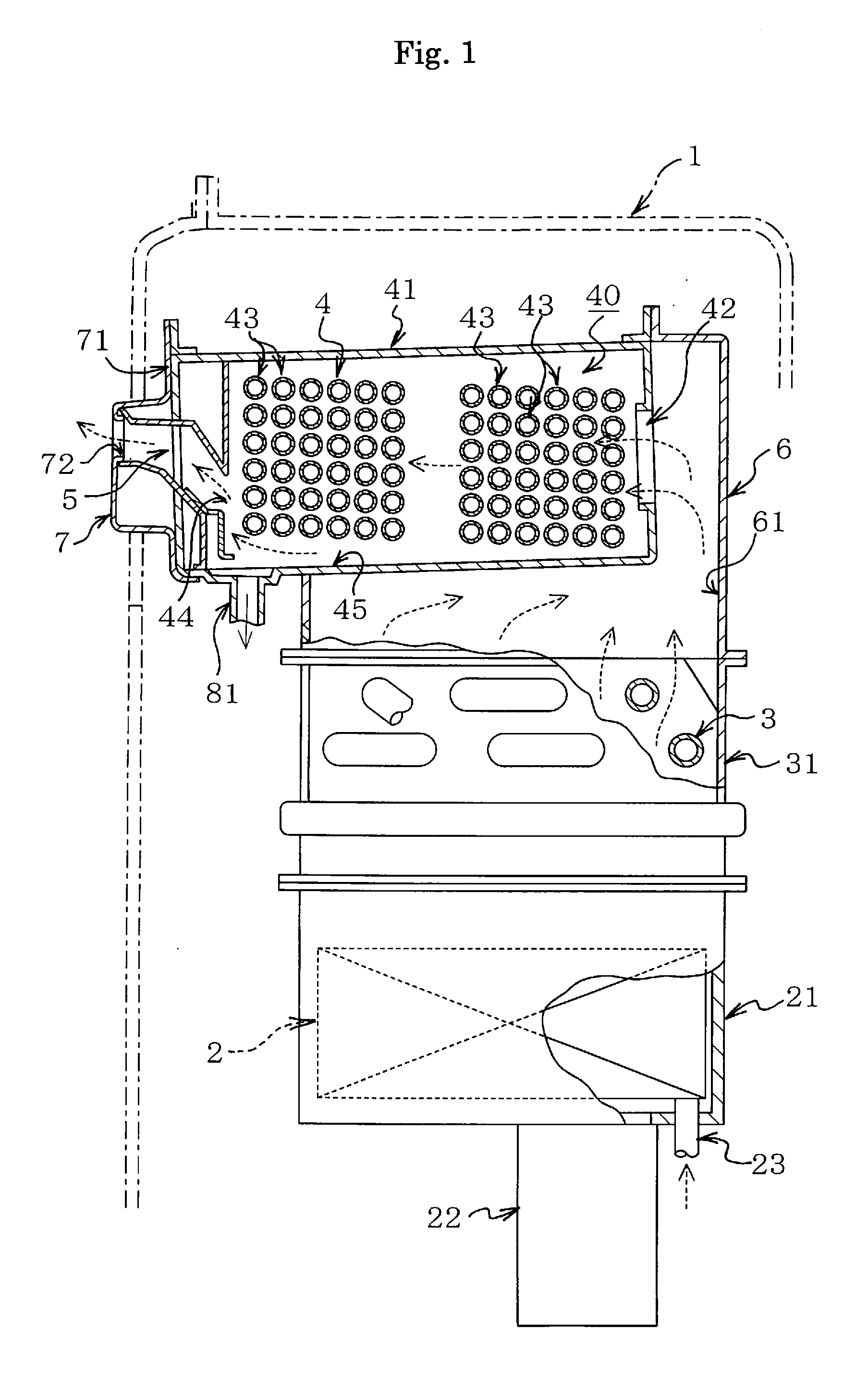
[0020]Referring first to FIG. 1, there is shown a part of a hot water supply heater serving as a combustion apparatus in accordance with an embodiment of the present invention. The hot water supply heater of FIG. 1 is configured as a so-called condensing-type (a latent heat recovery-type) hot water supply heater. More specifically, the combustion apparatus includes, in its housing 1, a combustion burner 2, a primary heat exchanger 3 for effecting heat-exchange heating by the heat of combustion (the sensible heat) of the combustion burner 2, a secondary heat exchanger (a latent heat exchanger) 4 for guiding the combustion exhaust past the primary heat exchanger 3 configured for the recovery of latent heat from the combustion exhaust and an exhaust channel 5 into and from which the combustion exhaust having passed through the secondary heat exchanger 4 is flowed and then dis...


PUM


Abstract

An exhaust channel of a combustion apparatus is defined by an upper sloping plate and a lower sloping plate. The lower sloping plate contains a rising part and a lower sloping wall. A water droplet baffle plate is positioned across an interspace from the rising part. The interspace is brought into fluid communication with the exhaust channel through an upper surface opening while being brought into fluid communication with a bottom of a heat exchange chamber through a communication opening. A collision wall part of the water droplet baffle plate is disposed in close proximity to a lowest fine tube so as to oppose against a combustion exhaust flow. Water droplets adhere onto the collision wall part. Water droplets failing to adhere to the collision wall part fall through the upper surface opening positioned over an upper end of the collision wall part.

Description

TECHNICAL FIELD[0001]The present invention relates to a combustion apparatus equipped with a latent heat exchanger (a heat exchanger for the recovery of latent heat). In particular, the present invention is concerned with technology for the prevention of scattering of the condensed water when combustion exhaust having passed through the latent heat exchanger is let off from the exhaust outlet port.BACKGROUND ART[0002]In recent years, there has been known a so-called condensing-type combustion apparatus made up of a primary heat exchanger (a sensible heat exchanger) configured for heat-exchange heating by the heat of combustion of a combustion burner and a secondary heat exchanger (a latent heat exchanger) configured for the recovery of latent heat from the combustion exhaust having undergone heat exchange in the primary heat exchanger. And, in such a condensing-type combustion apparatus, when combustion exhaust comes into contact with the latent heat exchanger, water vapor present i...

Claims


Application Information

Patent Timeline
IPC IPC(8): F24H1/22F22B1/18
CPCF22B1/18F24H1/40Y02B30/14F24D2200/18F24D12/02Y02B30/00
Inventor MAESHIMA, YUKIKODA, HIDEFUMI
Owner NORITZ CORP
Why Eureka
Eureka Blog
Learn More