System and method of clarifying drilling mud and a hydrophilic liquid or solution for use in clarifying drilling mud

a hydrophilic liquid and drilling mud technology, which is applied in the field of system and method of clarifying drilling mud and a hydrophilic liquid or solution for use in clarifying drilling mud, can solve the problems of substantial technical and economic problems in the oil drilling industry, and the use of the second decanter (b>2/b>) does not achieve the purpose of clarifying oil lubricant from the remaining solids and fines, so as to improve the recovery, improve the recovery, and the effect of the effect of the effect o

Inactive Publication Date: 2013-03-21
BLUE EAGLE HLDG
View PDF4 Cites 9 Cited by
  • Summary
  • Abstract
  • Description
  • Claims
  • Application Information

AI Technical Summary

Benefits of technology

[0014]It is the purpose of this invention to improve the clarification of oil mud to such an extent that recovery of diesel oil and/or other suitable oil lubricants is improved and/or optimized. The better the recovery, the more often such oil lubricants can be recycled. Achieving more efficient use of such oil lubricants, such as by increasing the number of times such oil lubricants may be recycled, saves substantial expenses related to the introduction and use of fresh lubricant oil. In addition, it becomes less likely tha

Problems solved by technology

However, as further discussed below, the use of the second decanter 14 (e.g., high speed Decanter-2) does not accomplish its purpose of clarifying the oil lubricant from the remaining solids and fines of the effluent after the first decanting step, e.g., the barite recovery step.
The oil drilling industry faces substantial technical and economical problems with the aforementioned recovery process.
The ever increasing concentration of fine solids can lead to disastrous results.
For example, the out-flowing oil mud may become so heavy and viscous (e.g., after the aforementioned effluent is recycled one or more times) that the drilling shaft gets stuck and can no longer be rotated or moved.
In many cases, the entire shaft and the very valuable drilling bit cannot be removed and are, consequently, entirely lost.
In other cases, it takes incredible efforts to finally recover the drilling shaft and the drilling bit.
Therefore, substantial time and/or money are lost.
In addition, ver

Method used


Image

  • System and method of clarifying drilling mud and a hydrophilic liquid or solution for use in clarifying drilling mud
  • System and method of clarifying drilling mud and a hydrophilic liquid or solution for use in clarifying drilling mud
  • System and method of clarifying drilling mud and a hydrophilic liquid or solution for use in clarifying drilling mud

Examples


example 1

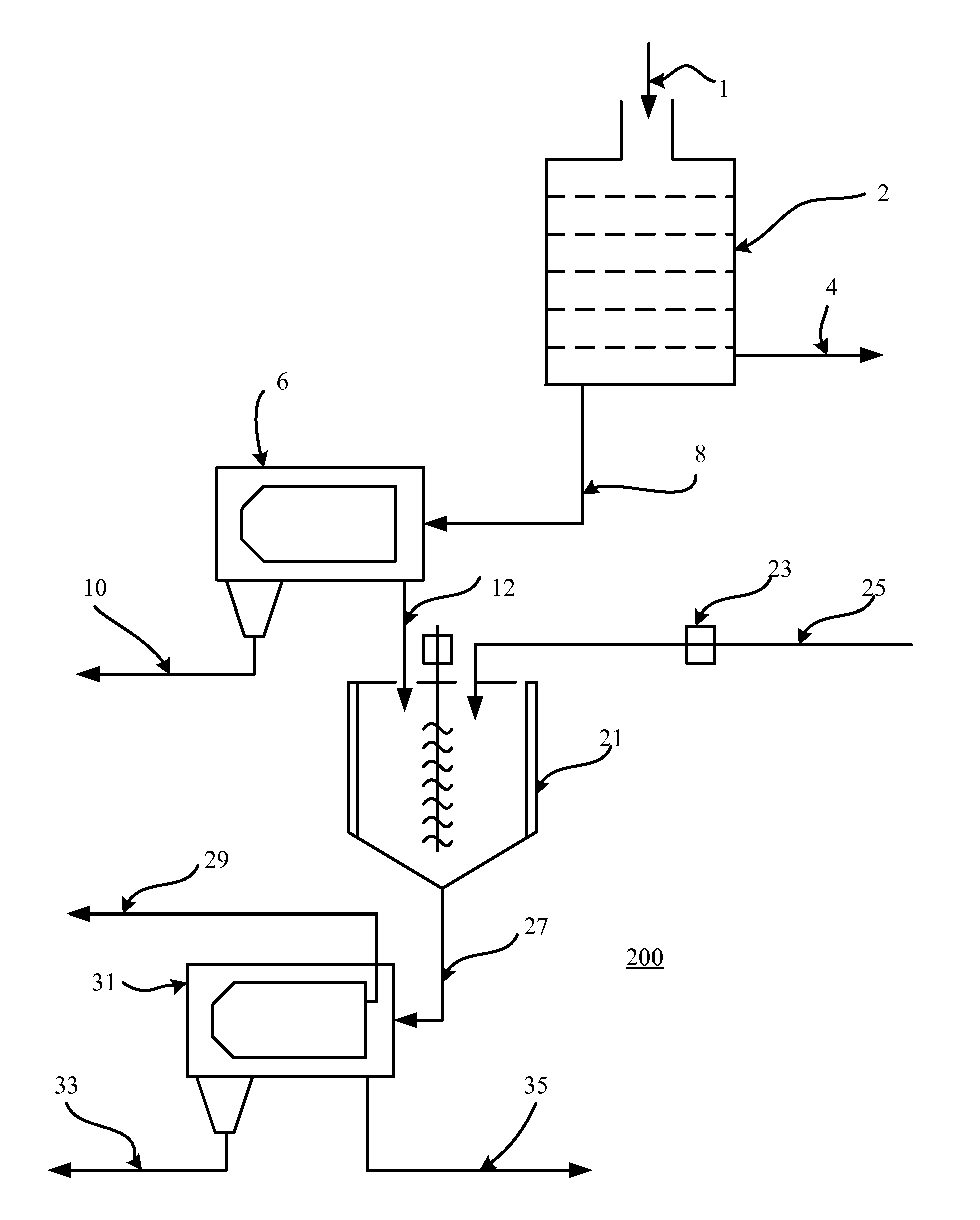
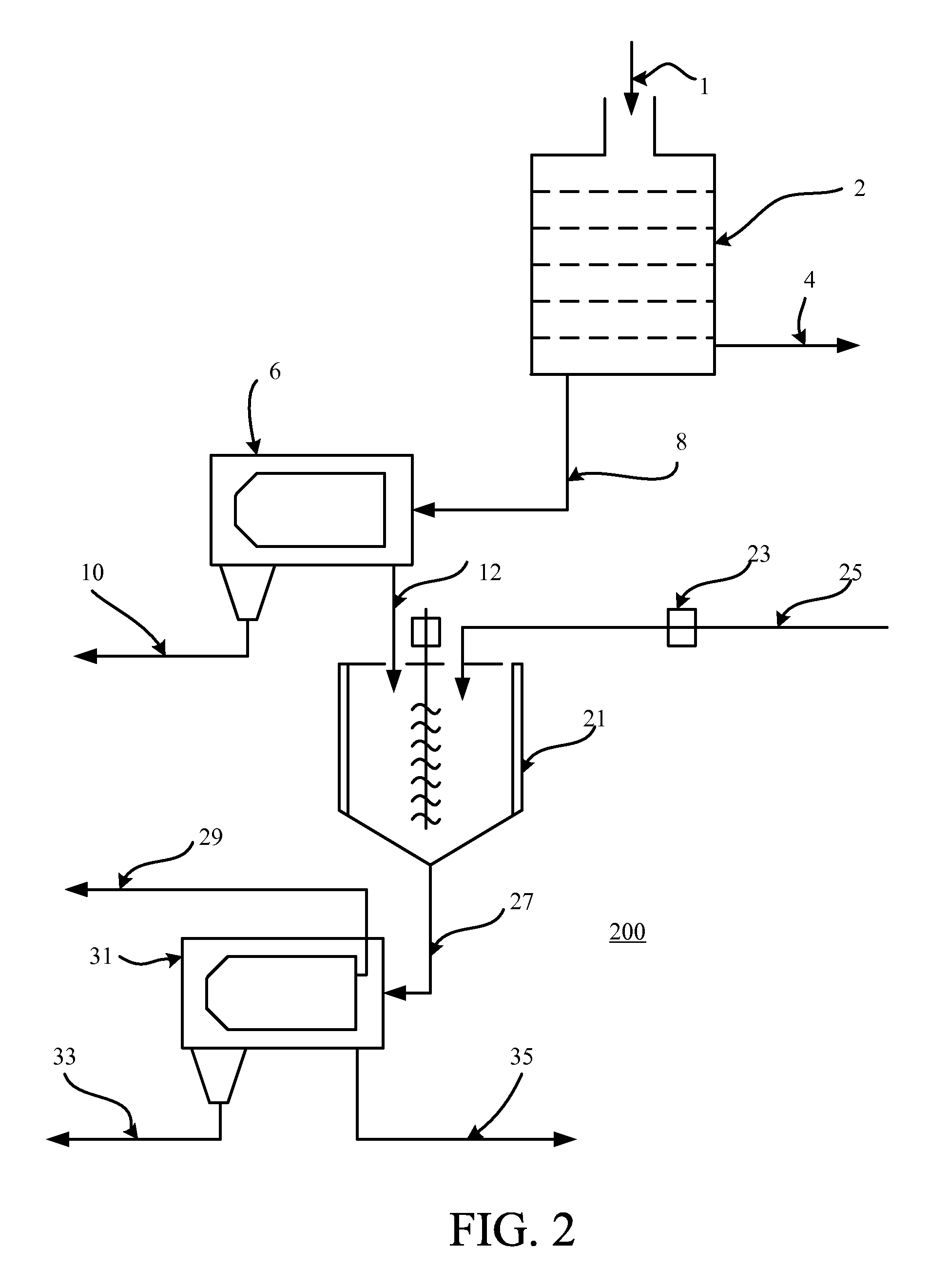
[0092]Drilling oil mud, which flows out of the Decanter 2 [see stage b2) as described before], has an average temperature of about 100° F. to 120° F. It is pumped into an insulated mixing tank (e.g., mixing tank 21), which is equipped with a high-speed mixer and then is mixed with the inventive Separation Liquid C in the following proportion:[0093]3,000 lb oil mud[0094]1,000 lb Liquid C[0095]4,000 lb

[0096]Liquid C is being heated to about 60° C. (about 140° F.) in a heat exchanger (e.g., heat exchanger 23) before entering the mixing tank (e.g., mixing tank 21).

[0097]Liquid C and oil mud, which has an average weight of 10.5 pound per gallon, are vigorously mixed to a uniform blend and charged into a Tricanter (e.g., tricanter 31) and separated at about 3,000 rpm. Almost all sediment solids, including fine solids, are discharged from the Tricanter (e.g., tricanter 31) at the opposite side of the liquid entry. The heavy-phase Liquid C is discharged under pressure (e.g., through output ...

example 2

[0101]Drilling oil mud which flows out of the Decanter 1 [see stage b1) as described before] has an average temperature of about 120° F.=49.9° C. and which has an average weight of 10.9 pound per gallon. It is pumped into an insulated mixing tank (e.g., mixing tank 21), which is equipped with a high-speed mixer and then is mixed with the inventive Separation Liquid F in the following proportion:[0102]2,800 lb oil mud[0103]1,200 lb Liquid F[0104]4,000 lb

[0105]Liquid F is being heated to about 60° C. (about 140° F.) in a heat exchanger (e.g., heat exchanger 23) before entering the mixing tank (e.g., mixing tank 21). Liquid F and oil mud are vigorously mixed to a uniform blend and charged into a Tricanter (e.g., tricanter 31) and separated at about 3,500 rpm. A thick sludge of sediment solids is discharged from the three stage decanter at the opposite side of the liquid entry. The heavy-phase Liquid F is discharged under pressure (e.g., through output 29) by adjusting the centripetal p...


PUM

PropertyMeasurementUnit
Temperatureaaaaaaaaaa

Abstract

Processes and systems are provided with a hydrophilic liquid or solution for clarifying drilling mud to separate diesel oil or other oil lubricants out from the drilling mud such that the diesel oil or other oil lubricants may be recycled to a well for reuse as a lubricant for drilling components, such as a drilling bit. The hydrophilic liquid or solution may be recovered and reused/recycled in the processes and/or systems as well.

Description

CROSS-REFERENCE TO RELATED APPLICATION(S)[0001]This application is a non-provisional patent application that claims the benefit of the filing date of, and priority to, U.S. Provisional Application No. 61 / 537,246, filed Sep. 21, 2011, the entirety of which is incorporated herein by reference.BACKGROUND OF THE INVENTION[0002]In the oil and gas exploration industry, drilling is the method of reaching the layers of fossil fuel, either on-shore or off-shore. One of the important parts of the drilling equipment is the rig, which consists of the extendible drilling shaft and the drilling bit. The drilling bit only works efficiently if lubricated.[0003]When dealing with lubricating the drilling bit to make the drilling process more efficient, lubrication liquids can be either water-based or oil-based. A preferred method of lubrication is the use of oil based lubricants, both for on shore and off shore drilling. During oil based drilling, diesel oil or other similar organic hydrocarbons or e...

Claims


Application Information

Patent Timeline
IPC IPC(8): E21B21/06B04B5/10B01D21/26C09K8/02C09K3/00B01D21/01
CPCB01D21/262C09K8/00E21B21/065B01D2221/04
Inventor SCHEIDE, JURGEN D.
Owner BLUE EAGLE HLDG
Why Eureka
Try Eureka