Lithium Ion Battery Control System and Assembled Battery Control System

Inactive Publication Date: 2013-03-21
HITACHI LTD
View PDF5 Cites 52 Cited by
  • Summary
  • Abstract
  • Description
  • Claims
  • Application Information

AI Technical Summary

Benefits of technology

[0029]According to the invention, it is possible to provide a lithium ion battery contro

Problems solved by technology

Accordingly, it is difficult to utilize the degradation suppressing method of setting the charging and discharging control in advance using the absolute value of

Method used


Image

  • Lithium Ion Battery Control System and Assembled Battery Control System
  • Lithium Ion Battery Control System and Assembled Battery Control System
  • Lithium Ion Battery Control System and Assembled Battery Control System

Examples


example 1

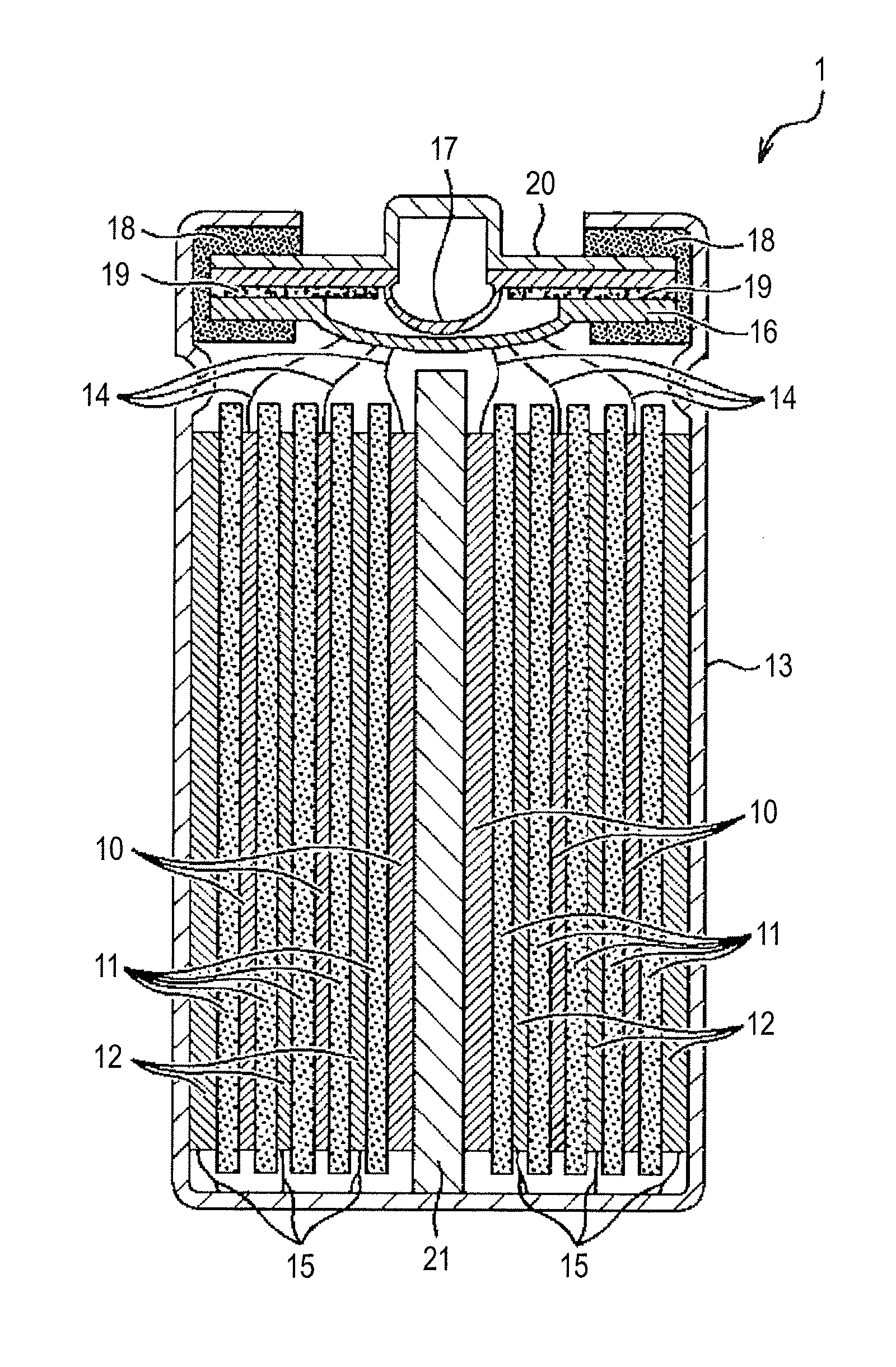
[0123]A lithium ion battery (battery) having the structure shown in FIG. 5 was first manufactured. Here, LiNi1 / 3Mn1 / 3Co1 / 3O2 was used as the positive-electrode active material and natural graphite (the distance between graphite layers (d002) measured through the X-ray structure analysis was 0.336 nm) was used as the negative-electrode active material. An aluminum foil was used as the positive electrode and a copper foil was used as the negative electrode.

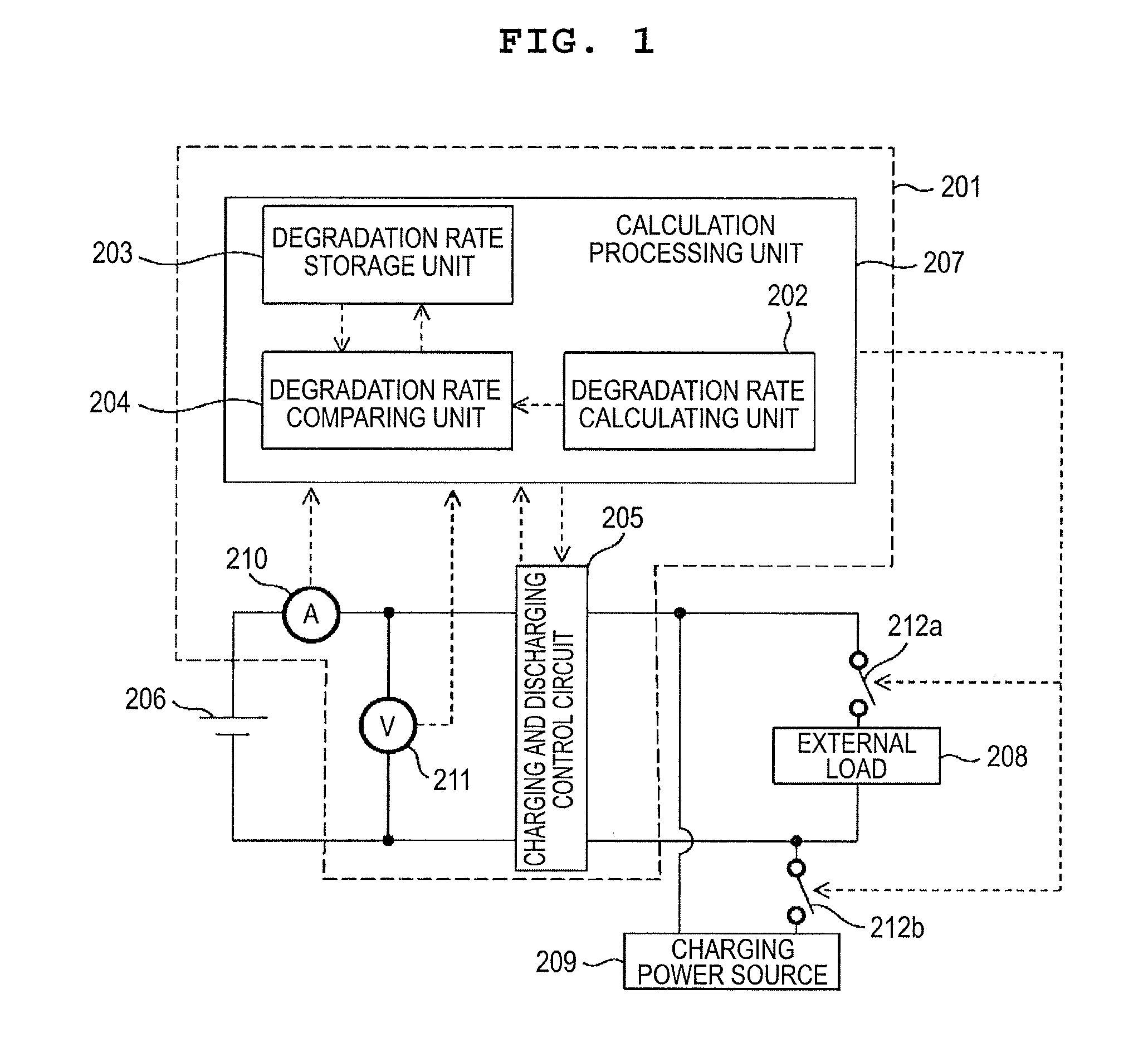
[0124]The manufactured battery as the battery 206 was charged by the use of the lithium ion battery control system shown in FIG. 1 and the battery characteristics were evaluated through the use of the below-described method. In the below-described method, degradation rates before and after charging and discharging the battery by a predetermined capacity were used as the present degradation rate and the previous degradation rate.

[0125]The manufactured battery was charged to 4.20 V with a current corresponding to 0.3 CA at the normal ...

example 2

[0134]Similarly to Example 1 except that the value of the constant power at the 1000-th cycle was changed from 8 W to 4 W, the cycle was repeated.

[0135]As a result, the degradation rate comparing unit made a correction in the 170-th, 450-th, 620-th, and 880-th cycles. The DC resistances at those times were 56.0 mΩ, 58.4 mΩ, 59.9 mΩ, and 62.2 mΩ, respectively.

[0136]Then, the battery capacity retention rate and the DC resistance increasing rate after 1000 cycles were calculated. The results are shown in Table 1. The initial battery capacity was 1.150 Ah, the initial DC resistance was 54.5 mΩ, the battery capacity after 1000 cycles was 0.987 Ah, and the DC resistance after 1000 cycles was 63.2 mΩ.


PUM


Abstract

A lithium ion battery control system includes a degradation rate calculating unit, a degradation rate storage unit, a degradation rate comparing unit, a charging and discharging control circuit, and a rechargeable battery. The degradation rate calculating unit calculates a degradation rate when receiving a trigger for starting the check of the degradation rate of the battery. The degradation rate comparing unit receives a present degradation rate from the degradation rate calculating unit and a previous degradation rate from the degradation rate storage unit and compares both degradation rates. As a result, when the present degradation rate is greater than the previous degradation rate by a predetermined value, a charging and discharging condition is limited.

Description

BACKGROUND OF THE INVENTION[0001]1. Field of the Invention[0002]The present invention relates to a lithium ion battery control system controlling charging and discharging of a lithium ion battery.[0003]2. Background Art[0004]Since they have a high energy densities, lithium ion batteries have attracted attention as batteries used in vehicles such as railroad cars and automobiles or used to store power generated through photovoltaic power generation or wind power generation and to supply the power to power systems. For example, when a lithium ion battery (hereinafter, appropriately referred to as “battery”) is mounted on a vehicle, examples of such a vehicle include zero-emission electric vehicles without an engine mounted, hybrid electric vehicles with both an engine and a rechargeable battery mounted, and plug-in hybrid electric vehicles charged directly from a system power source. Such batteries are expected to be used in a stationary power storage system supplying power at the tim...

Claims


Application Information

Patent Timeline
IPC IPC(8): H02J7/00
CPCH01M10/0525Y02T10/7005H01M10/44H01M10/441B60L11/1803B60L11/1857B60L11/1866B60L11/1879B60L2240/545B60L2240/547B60L2240/549Y02E60/122Y02T10/7061Y02T10/7011G01R31/3679B60L2200/26H01M10/425B60L50/51B60L58/16B60L58/22B60L50/64G01R31/392Y02E60/10Y02T10/70
Inventor TANAKA, AKIHIDENISHIMURA, ETSUKO
Owner HITACHI LTD
Why Eureka
Try Eureka