

Double-walled tube with interface gap and production method therefor
a technology of interface gap and double-walled tube, which is applied in the direction of greenhouse gas reduction, nuclear elements, lighting and heating apparatus, etc., can solve the problems of reaction and explosion, double-walled tube with interface gap according to such prior art requires very special, intricate and elaborate processing, etc., to prevent through-wall leakage, high temperature strength, and produce quickly and stably
- Summary
- Abstract
- Description
- Claims
- Application Information
AI Technical Summary
Benefits of technology
Problems solved by technology
Method used
Image

Examples
examples
[0061]As outer and inner wall tubes for producing a double-walled tube, seamless tubes of JIS standard STBA24 (2.25Cr-1Mo) which is a conventional heat-resistant steel containing not less than 2% of Cr, ASME standard T91 (9Cr-1Mo—V—Nb), and JIS standard SUS321HTB (18Cr-10Ni—Ti) were prepared. The dimensions of respective tubes were as follows.
[0062]Outer wall tube: Outside diameter 20.4 mm, wall thickness 1.9 mm, and length 15 m
[0063]Inner wall tube: Outside diameter 15.7 mm, wall thickness 1.6 mm, and length 15 m
[0064]Using these seamless steel tubes, tubes in which an oxide scale is formed in advance in the inner surface or the outer surface thereof, and tubes in which the surface (inner or outer surface) thereof to be the counterpart of the aforementioned tube was machined and ground were prepared in combination of the outer and inner wall tubes as shown in Table 1.
TABLE 1Production MethodReduction rateMaterial UsedScale thicknessMachining andof drawing ofPrototypebefore drawingg...
PUM
| Property | Measurement | Unit |
|---|---|---|
| thickness | aaaaa | aaaaa |
| thickness | aaaaa | aaaaa |
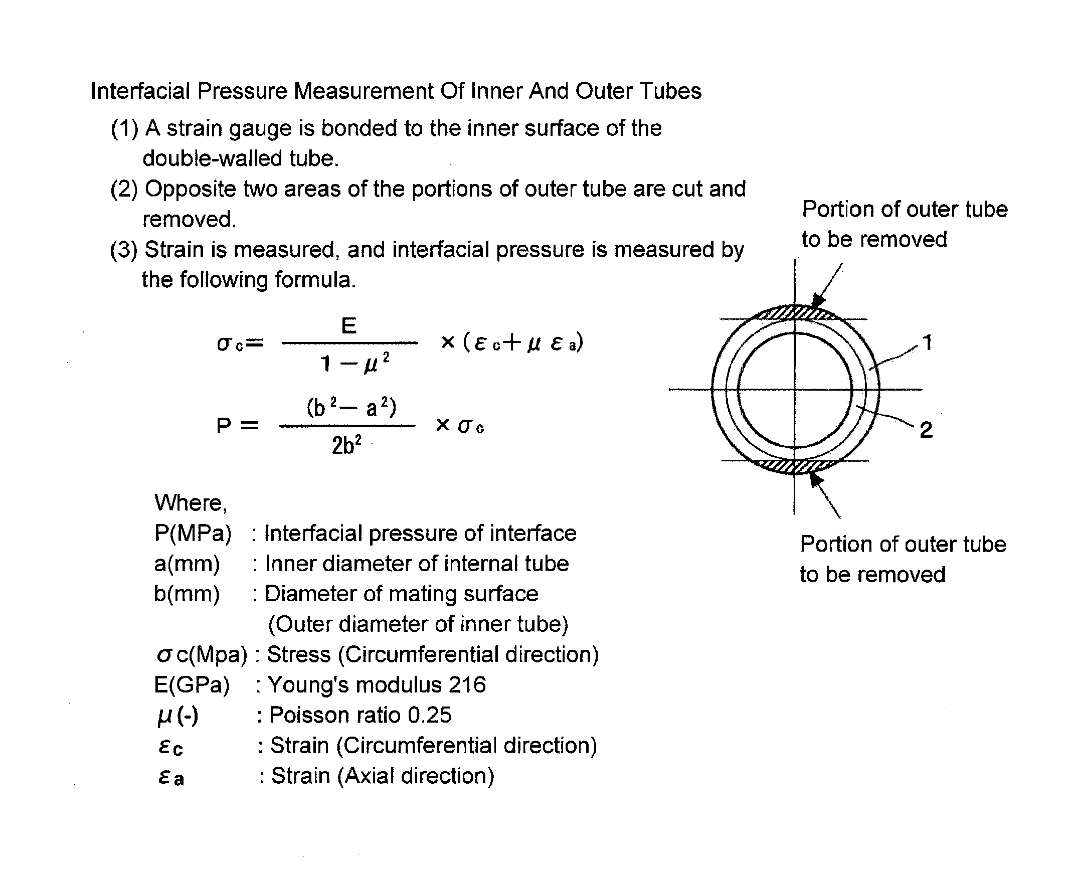
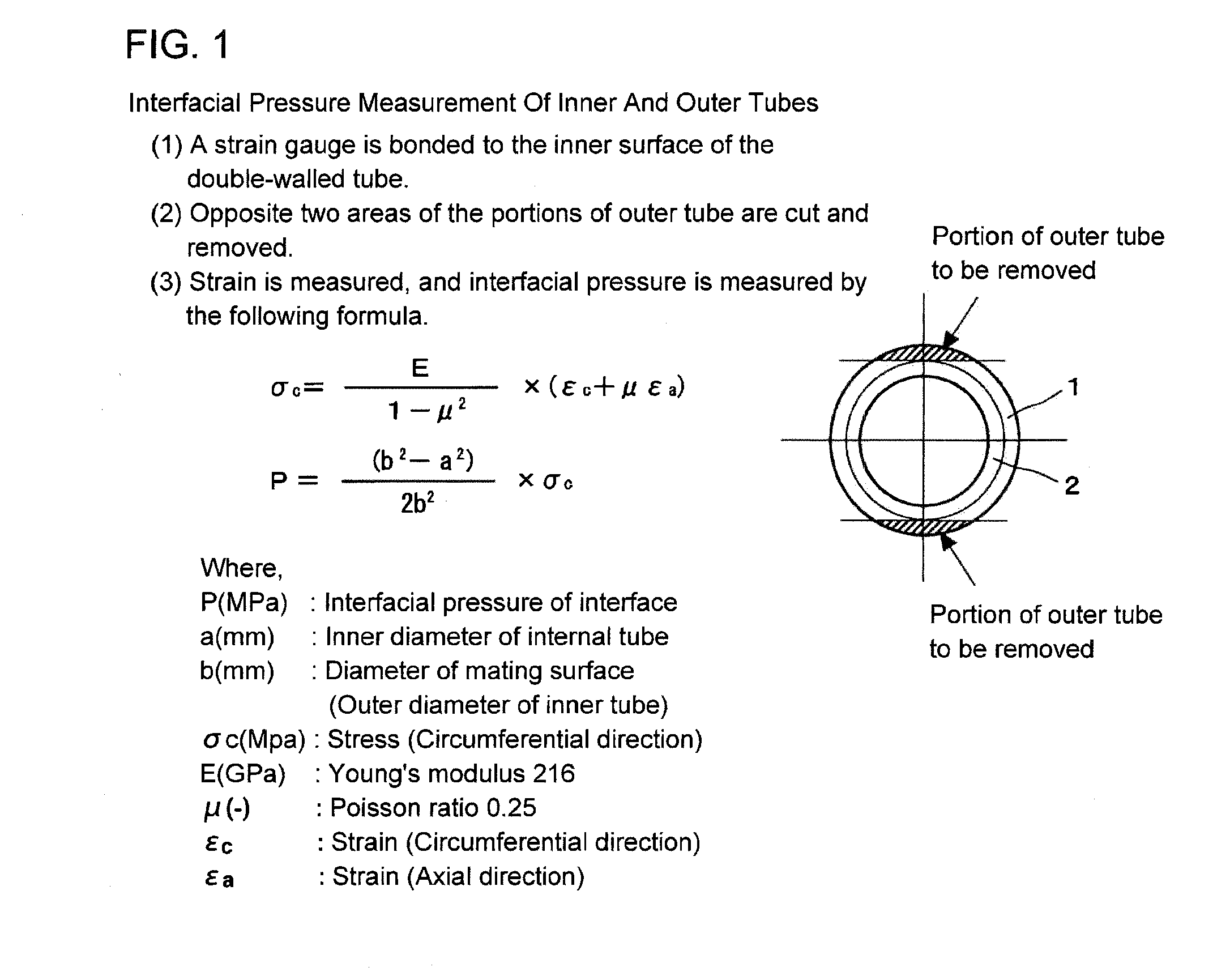
| interfacial pressure | aaaaa | aaaaa |
Abstract
Description
Claims
Application Information