
Metal artifacts reduction for cone beam ct

a technology of computed tomography and metal artifacts, applied in the field of diagnostic imaging, can solve the problems of reducing image quality, falsifying ct values, and difficult or impossible to effectively use the reconstructed image in assessing patient condition or properly planning radiation therapy or other suitable treatments, so as to reduce computational demands, improve overall efficiency of the process, and reduce the effect of metal artifacts

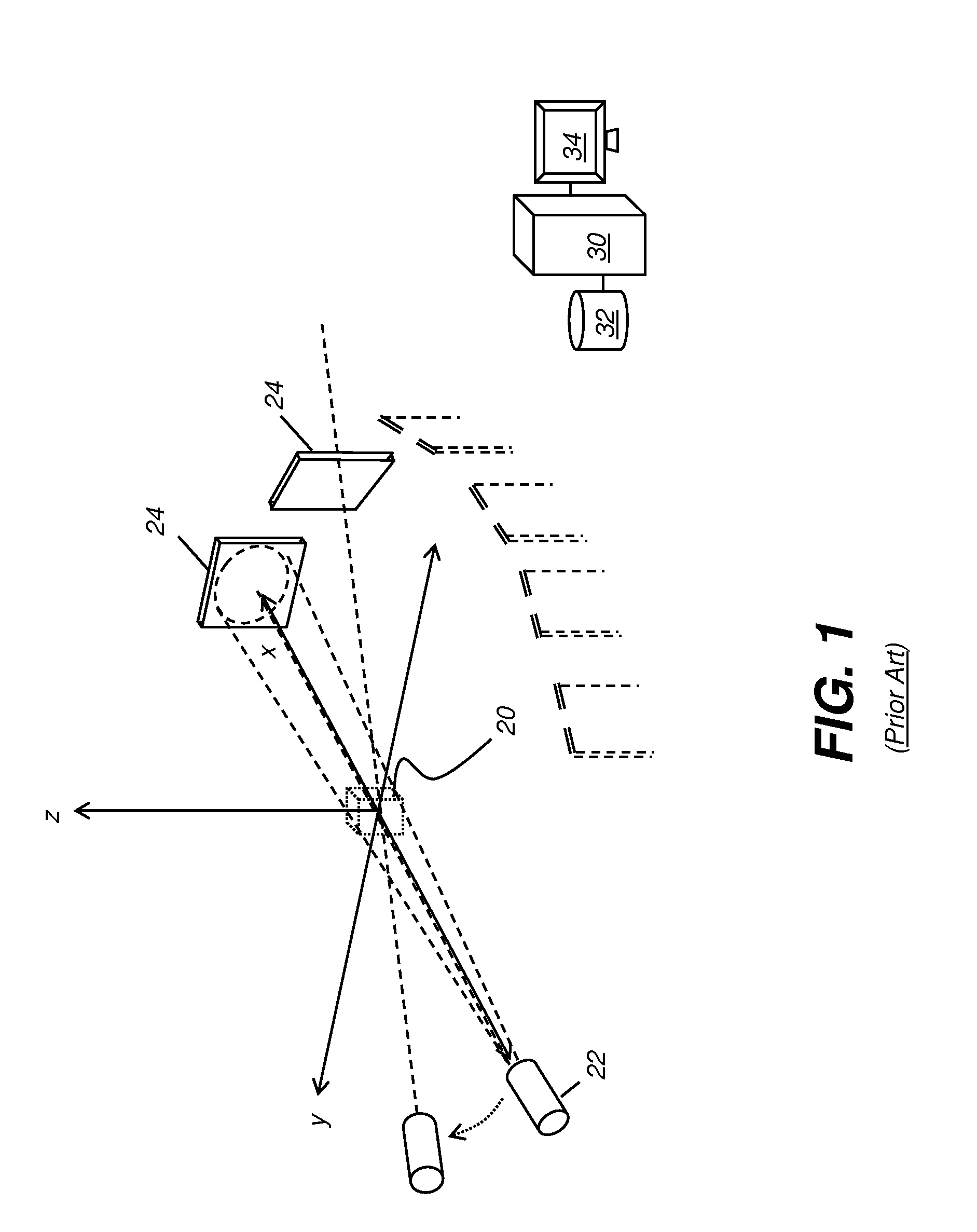
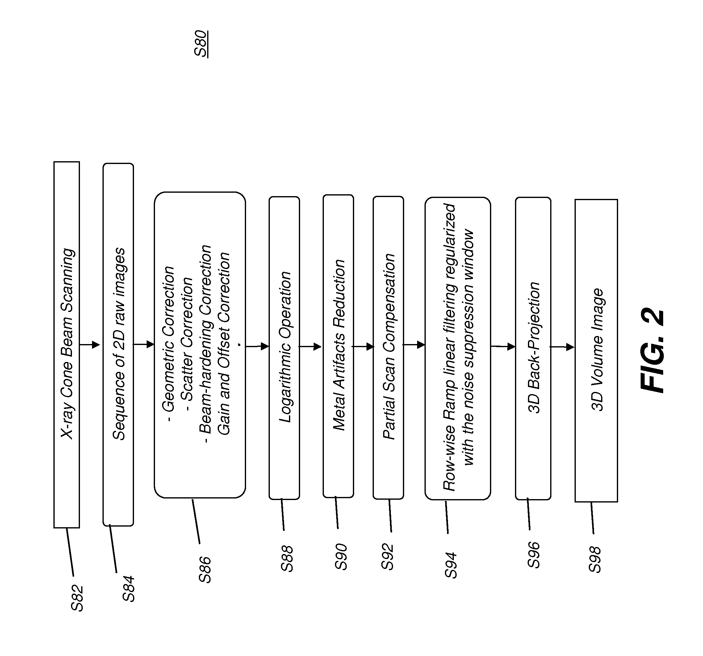
Active Publication Date: 2013-03-21
CARESTREAM HEALTH INC
View PDF11 Cites 31 Cited by
  • Summary
  • Abstract
  • Description
  • Claims
  • Application Information

AI Technical Summary

Benefits of technology

The patent text describes a method to improve the quality of CBCT images by reducing metal artifacts. This can be done by processing the projection data to increase efficiency and reduce computational demands. The technical effect is to provide a better quality CBCT image with reduced metal artifacts.

Problems solved by technology

Although 3-D images of diagnostic quality can be generated using CBCT systems and technology, a number of technical challenges remain.
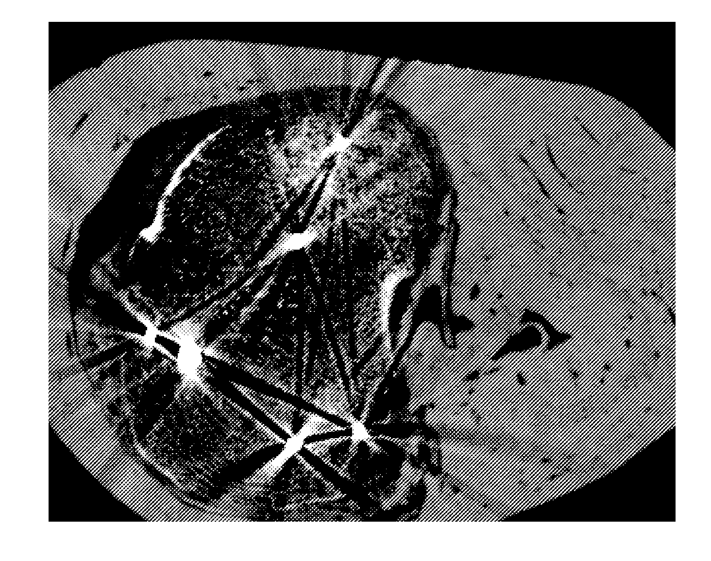
Highly dense objects, such as metallic implants, appliances, surgical clips and staples, dental fillings, and the like can cause various image artifacts that can obscure useful information about the imaged tissue.
Such artifacts can be due to physical effects such as high quantum noise, radiation scatter, beam hardening, and non-linear amplification in FBP reconstruction.
These artifacts can reduce image quality by masking soft tissue structures, not only in the immediate vicinity of the dense object, but also throughout the entire image.
At worst, this can falsify CT values and even make it difficult or impossible to use the reconstructed image effectively in assessing patient condition or to properly plan radiation therapy or other suitable treatments.
However, in more complex heterogeneous tissue, particularly where there are multiple metal objects in a heterogeneous volume, the interpolation-based algorithm can make unrealistic assumptions about the volume segment that lies in the shadow of the object(s), leading to prominent errors in the reconstructed images.
These requirements are easily met for computer simulation or phantom imaging, and have been experimentally tested by researchers; however, iterative reconstruction may be impractical for clinical use, where volume geometries are considerably more complex than those used in simulation.
Furthermore, iterative reconstruction methods are computationally much more intensive than FBP, making these methods less practical for clinical use in commercial CT scanning apparatus.3. Quasi-iterative based FBP approach.
However, one drawback of this method is that it fails whenever the interpolation based approach (1) fails.
Moreover, quasi-iterative processing cannot handle the case where the object size exceeds the field of view, since additional artifacts caused by the forward projection are introduced in the corrected images.
It is recognized that metal artifacts reduction can be a challenging task, particularly for more complex implant geometries.

Method used


Image

  • Metal artifacts reduction for cone beam ct
  • Metal artifacts reduction for cone beam ct
  • Metal artifacts reduction for cone beam ct

Examples


Embodiment Construction

[0026]The following is a detailed description of preferred embodiments of the invention, reference being made to the drawings in which the same reference numerals identify the same elements of structure in each of the several figures.

[0027]In the drawings and text that follow, like components are designated with like reference numerals, and similar descriptions concerning components and arrangement or interaction of components already described are omitted. Where they are used, the terms “first”, “second”, and so on, do not necessarily denote any ordinal or priority relation, but are simply used to more clearly distinguish one element from another.

[0028]In the context of the present disclosure, the term “volume image” is synonymous with the terms “3-dimensional image” or “3-D image”. Embodiments of the present invention are particularly well suited for suppressing the types of metal artifacts that occur in 3-D volume images, including cone-beam computed tomography (CBCT) as well as ...


PUM


Abstract

A method for suppressing metal artifacts in a radiographic image, the method executed at least in part on a computer, obtains at least one two-dimensional radiographic image of a subject, wherein the subject has one or more metal objects and identifies a material that forms the one or more metal objects and a radiation energy level used to generate the obtained image. The obtained radiographic image is segmented to identify boundaries of the metal object. A conditioned radiographic image is formed by replacing pixel values in the radiographic image that correspond to the one or more metal objects with compensating pixel values according to the identified material and the identified radiation energy level. The conditioned radiographic image is then displayed.

Description

FIELD OF THE INVENTION[0001]The invention relates generally to the field of diagnostic imaging and in particular to Cone-Beam Computed Tomography (CBCT) imaging. More specifically, the invention relates to a method for improving CBCT results by reducing metal artifacts in the reconstructed image.BACKGROUND OF THE INVENTION[0002]3-D volume imaging has proved to be a valuable diagnostic tool that offers significant advantages over earlier 2-D radiographic imaging techniques for evaluating the condition of internal structures and organs. 3-D imaging of a patient or other subject has been made possible by a number of advancements, including the development of high-speed imaging detectors, such as digital radiography (DR) detectors that enable multiple images to be taken in rapid succession.[0003]Cone beam computed tomography (CBCT) or cone beam CT technology offers considerable promise as one type of diagnostic tool for providing 3-D volume images. Cone beam CT systems capture volume da...

Claims


Application Information

Patent Timeline
Patent Type & Authority Applications(United States)
IPC IPC(8): G06K9/00
CPCG06T11/008A61B6/5258G06F3/00G06V40/16G06V40/113G06V40/20
Inventor YANG, DONGSENN, ROBERT A.
Owner CARESTREAM HEALTH INC
Learn More