
Partially Impregnated, Fiber Reinforced Thermoplastic Strength Member

a technology of thermoplastic strength member and fiber, which is applied in the direction of optical elements, instruments, coatings, etc., can solve the problems of difficult installation of fiber optic cables comprising these strength members, limited process speed, and relatively high cost and weight, and achieve the effect of improving cable flexibility

Active Publication Date: 2013-03-21
DOW GLOBAL TECH LLC
View PDF21 Cites 1 Cited by
  • Summary
  • Abstract
  • Description
  • Claims
  • Application Information

AI Technical Summary

Benefits of technology

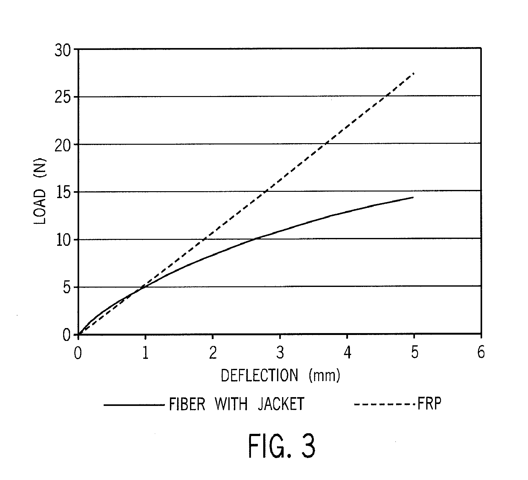
The fiber bundle described in this patent has several technical benefits. First, it has reduced bending stiffness and improved manufacturing efficiency compared to traditional fiber bundles that are fully impregnated with resin. Second, the fiber bundle provides strength for fiber optic cables and other wire and cable applications. Third, the volume ratio between the bundle fiber / resin composite layer and the center loose fibers can be adjusted to tailor the bending and torsion stiffness of the bundle. Fourth, water blocking coatings can be added to the fibers to enhance water blocking characteristics. Fifth, wire jacket extrusion lines have much higher line speeds, leading to greater manufacturing efficiency compared to traditional fiber pultrusion processes. Lastly, the fiber bundles can be used in applications where high tensile modulus in one direction is desired.

Problems solved by technology

Traditionally, FRP or GRP is manufactured through a fiber pultrusion process with one or more thermoset resins such as vinyl ester or epoxy, but the speed of process is very limited.
As for stainless steel, it is relatively expensive and heavy.
In addition, the GRP or FRP / thermoset resin composites available today tend to have excessive stiffness, and this makes installation of fiber optic cable comprising these strength members difficult, especially around buildings or along busy city streets where sharp bending of the cable is often necessary.

Method used


Image

  • Partially Impregnated, Fiber Reinforced Thermoplastic Strength Member
  • Partially Impregnated, Fiber Reinforced Thermoplastic Strength Member
  • Partially Impregnated, Fiber Reinforced Thermoplastic Strength Member

Examples


specific embodiments

[0054]Materials

[0055]The fiber is SPECTRA® 900, an ultra high molecular weight polyethylene yarn of 1,200 denier and 120 filament available from Honeywell. The melting temperature of the fiber is 150° C. and other properties of the fiber are reported in Table 1.

[0056]The resin is ENGAGE® 8200EG polyolefin elastomer, an ethylene-octene copolymer with a density of 0.870 g / cc, a melt index of 5 g / 10 min, a melt point of 60° C. and available from The Dow Chemical Company.

TABLE 1Properties of SPECTRA ® 900 FiberWeight / Unit Length (Denier)65012004800(Decitex)72213335333Ultimate Tensile Strength (g / den)30.53025.5(Gpa)2.62.572.18Breaking Strength (lbs.)4479270Modulus (g / den)920850885(Gpa)797375Elongation (%)3.63.93.6Density (g / cc)0.970.970.97(lbs / in3)0.0350.0350.035Filament / tow60120480Filament (dpf)10.810.010.0

[0057]Method of Bundle Construction

[0058]The fiber bundle is constructed using a mini-wire line extruder with a five horsepower motor and four heating zones. The fiber and resin are m...


PUM

PropertyMeasurementUnit
Fractionaaaaaaaaaa
Fractionaaaaaaaaaa
Fractionaaaaaaaaaa

Abstract

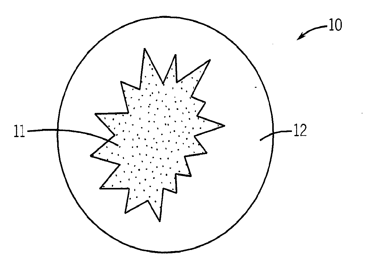
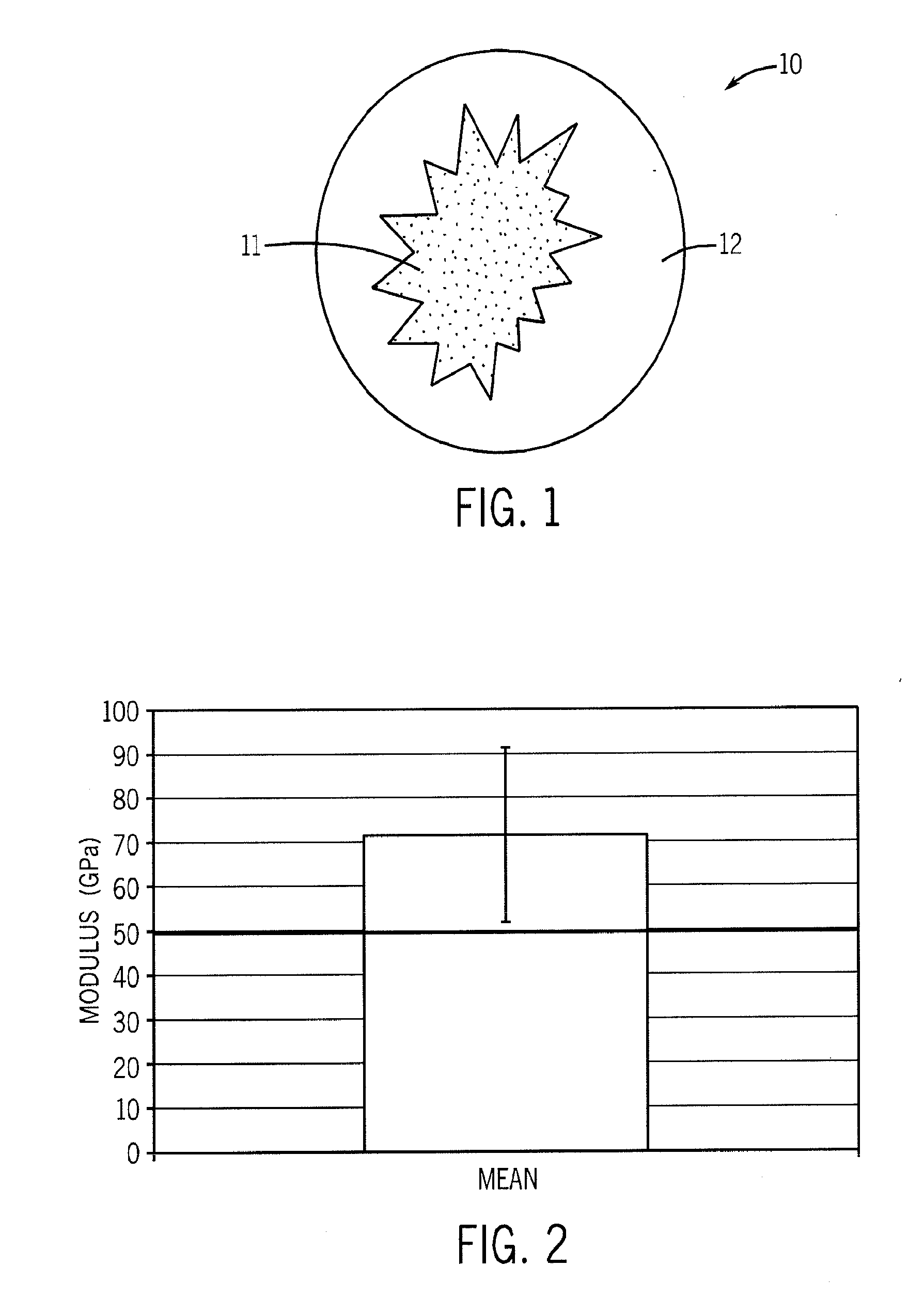
Fiber bundles (10) comprise loose fibers (11) encased within a fiber / resin composite (12). The bundles are useful as strength members for fiber optic cables. In one embodiment the bundles are prepared by a method comprising the steps of (A) bundling fibers together such that a portion of the fibers form an interior part of the bundle and a portion of the fibers form an exterior part of the bundle, and (B) impregnating the exterior part of the bundle with a resin such that (1) the fibers that form the exterior part of the bundle and the resin form a fiber / resin composite that encases the fibers that for the interior part of the bundle, and (2) the fibers that form the interior part of the bundle are not impregnated with the resin.

Description

BACKGROUND OF THE INVENTION[0001]1. Field of the Invention[0002]This invention relates to wire and cable. In one aspect the invention relates to a strength member of a wire or cable while in another aspect, the invention relates to a strength member that is fiber reinforced. In yet another aspect the invention relates to a process for making a fiber reinforced strength member while still in another aspect, the invention relates to wire and cable comprising a fiber reinforced strength member.[0003]2. Description of the Related Art[0004]Fiber-optic cable is a complex structure designed to provide sufficient protection for the fibers from detrimental levels of longitudinal and transverse stresses. In addition, the structure also provides a benign chemical and physical environment for the service life of the fibers. One fundamental difference between fiber-optic cable and electrical power cable is that the metal conductors in a power cable carry at least portion of the tensile stresses ...

Claims


Application Information

Patent Timeline
IPC IPC(8): G02B6/44
CPCB29B15/122G02B6/4401G02B6/4434D01D5/28D01D5/34G02B6/44
Inventor CHEN, BUOVAN POUCKE, JEROEN
Owner DOW GLOBAL TECH LLC
Learn More