Proton-exchange membrane fuel cell electrode structuration

Active Publication Date: 2013-03-21
COMMISSARIAT A LENERGIE ATOMIQUE ET AUX ENERGIES ALTERNATIVES
View PDF2 Cites 3 Cited by
  • Summary
  • Abstract
  • Description
  • Claims
  • Application Information

AI Technical Summary

Benefits of technology

[0038]All these solutions aim at increasing the hydrophobic character of the active layer. However, such processings may be subject to chemical degradation mechanisms after several hundreds of hours of use. Further, the introduction of an additional product may decre

Problems solved by technology

This approach goes against that of those skilled in the art, which would tend t

Method used


Image

  • Proton-exchange membrane fuel cell electrode structuration
  • Proton-exchange membrane fuel cell electrode structuration
  • Proton-exchange membrane fuel cell electrode structuration

Examples


embodiment

OF EMBODIMENT

[0062]The foregoing features and advantages of the present invention will be discussed in the following non-limiting description of the following embodiments in connection with the accompanying drawings.

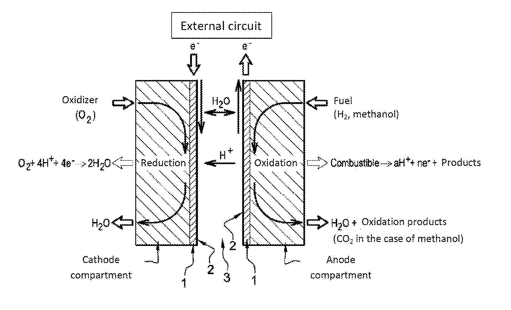
[0063]FIG. 1 shows the simplified operating diagram of a PEMFC fuel cell.

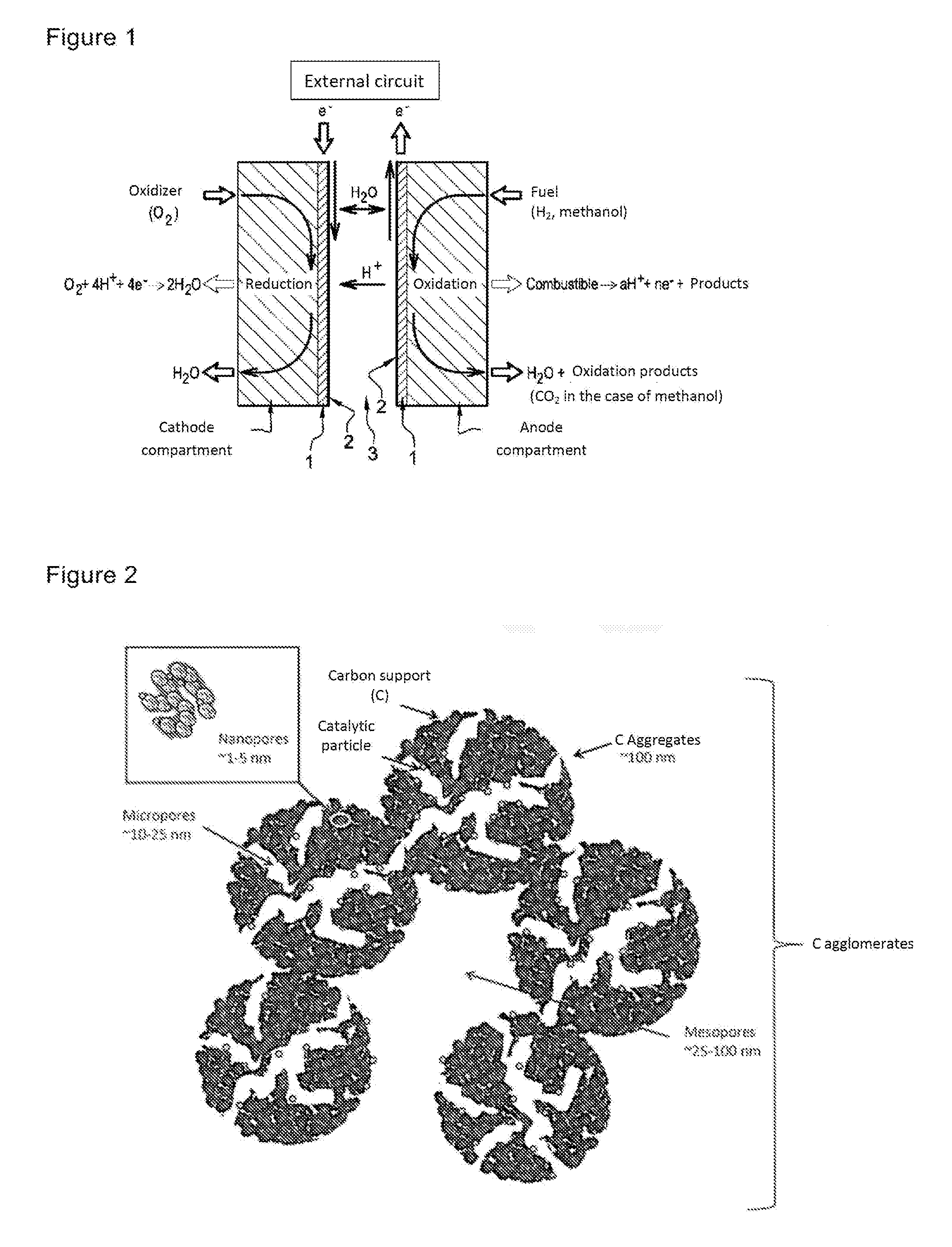
[0064]FIG. 2 shows the diagram of the structure of a PEMFC fuel cell electrode.

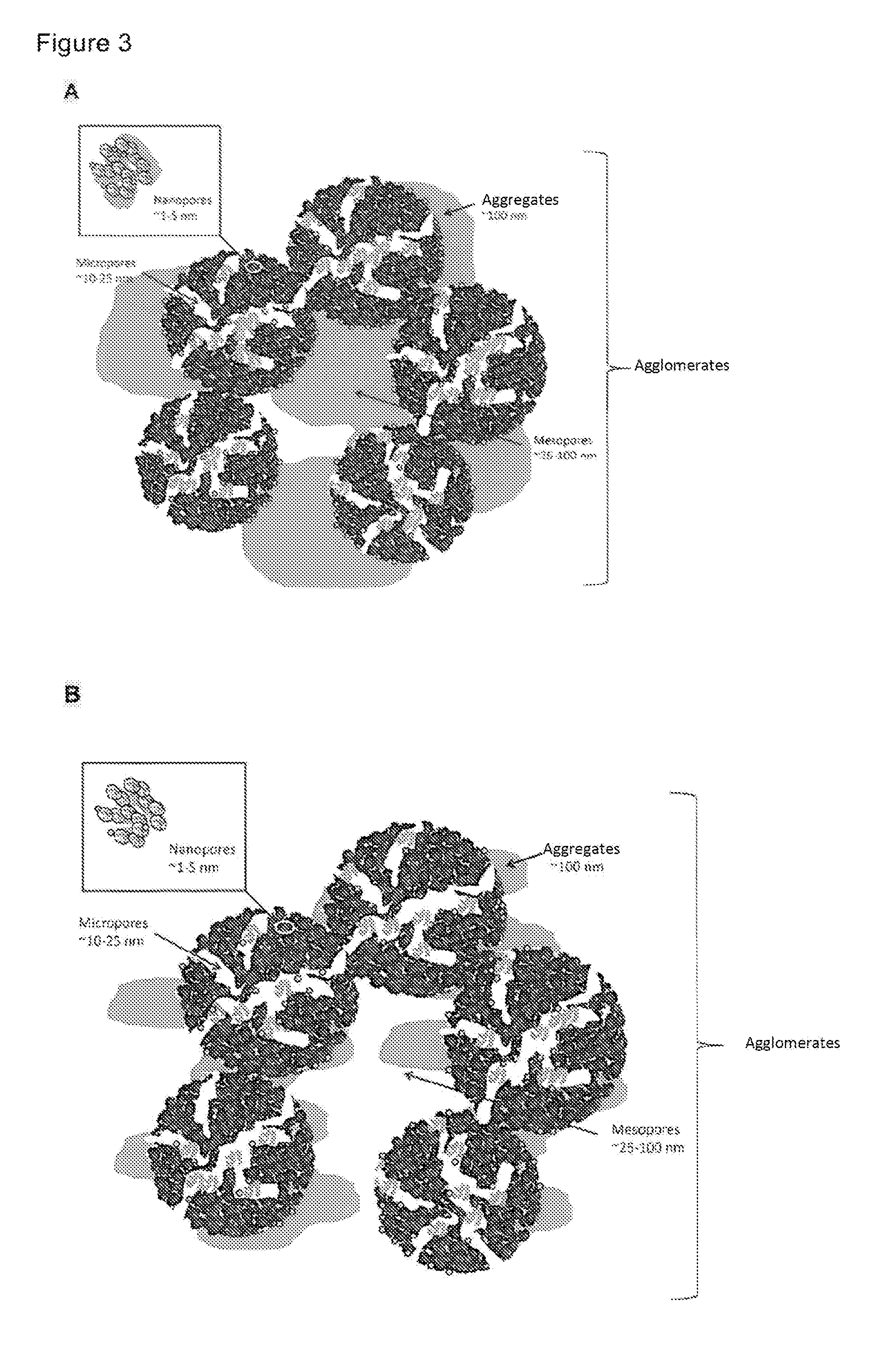
[0065]FIG. 3 illustrates the lesser capacity of an electrode according to the present invention to flood (B) and to cause the electrochemical aging of the catalytic nanoparticles and the degradation of the carbon support. FIG. 3B illustrates an MEA according to the present invention containing less platinum than the MEA shown in FIG. 3A.

[0066]Six membrane-electrode assemblies (MEA [1] to [6]) have been prepared and tested.

[0067]The test results (response of the cell potential along time) are illustrated in FIGS. 4 to 9.

[0068]FIG. 10 shows the variation of the voltage and of the current density along time for a fuel cell c...


PUM


Abstract

An electrode for an electrochemical system, such as a fuel cell, is formed by an active layer including: pores; at least one catalyst; at least one ionomer; and electrically-conductive particles. The catalyst content per pore ranges between 30 and 500 mg/cm3 with respect to the pore volume.

Description

TECHNICAL FIELD[0001]The present disclosure relates to the field of proton exchange membrane fuel cells, and more specifically to the structuring of the electrodes forming them.[0002]Proton exchange membrane fuel cells, as current generators, have a wide range of applications.BACKGROUND OF THE INVENTION[0003]The operating principle of proton exchange membrane fuel cells (PEMFC) is based on the conversion of chemical energy into electric energy by catalytic reaction between the fuel (hydrogen) and the oxidizer (oxygen).[0004]Membrane-electrode assemblies (MEAs), commonly called cell cores, form the base elements of PEMFCs. As illustrated in FIG. 1, the MEA is generally formed of a polymer membrane (electrolyte, 3) in contact with a catalytic layer (electrodes, 2) on both sides. The electrodes (anode and cathode) are thus separated by the electrolyte, which is an insulating for electrons but however conducts protons. Current collectors (1) ensure the electron transfer at the external ...

Claims


Application Information

Patent Timeline
IPC IPC(8): H01M4/86H01M4/88H01M8/10H01M4/92H01M4/96
CPCB82Y30/00H01M4/8605H01M4/8663H01M4/8673H01M4/8828Y10S977/742H01M2008/1095Y02E60/50H01M4/925H01M4/96H01M8/10H01M4/926H01M4/86H01M4/88H01M4/9008H01M4/92H01M4/921H01M8/0226
Inventor VINCENT, REMIESCRIBANO, SYLVIEFRANCO, ALEJANDRO
Owner COMMISSARIAT A LENERGIE ATOMIQUE ET AUX ENERGIES ALTERNATIVES
Why Eureka
Try Eureka