System and methods for thermal isolation of components used

a technology of thermal isolation and components, applied in the direction of heat dissipation, fire prevention, washing machines, etc., can solve the problems of large moment of force and shear force, damage and failure of building components, loss of insulating properties, etc., and achieve the effect of preventing the conduction of thermal energy

Active Publication Date: 2013-03-28
KNIGHT WALL SYST +1
View PDF47 Cites 20 Cited by
  • Summary
  • Abstract
  • Description
  • Claims
  • Application Information

AI Technical Summary

Benefits of technology

[0015]Disclosed herein is an isolator system for preventing the conduction of thermal energy between two metal components of a wall assembly comprising: an isolator plate for placement between a wall stud and a fastening member having a surface area adapted to be placed in communication with said wall stud, said plate comprised of an insulatin

Problems solved by technology

The weight of a façade or exterior cladding installed over several inches of insulation can create a large moment of force and shear force which act on fasteners extending through materials positioned between studs and the exterior cladding.
Ineffective fasteners can creep over time, resulting in building component damage and failures.
For example, if fastening systems do not protect the interior insulating layers against the forces exerted by exterior layers, insulating materials can be crushed or deformed and lose insulating properties.
Unfortunately, cladding fastening systems also tend to undermine the effectiveness of the exterior insulation by creating thermal bridges, commonly lowering the effective R-value of the completed wall assembly to less than required by the energy codes and standards.
Designers, contractors and code officials often mistakenly equate the insulation R value and the wall R value and do not recognize that the metal conducts heat well and significantly reduces the R value of the actual wall below the R value of the insulation itself.
This phenomena is also known as a “fin effect.” As a result, the wall in question will have an inadequate R-value and th

Method used


Image

  • System and methods for thermal isolation of components used
  • System and methods for thermal isolation of components used
  • System and methods for thermal isolation of components used

Examples


Embodiment Construction

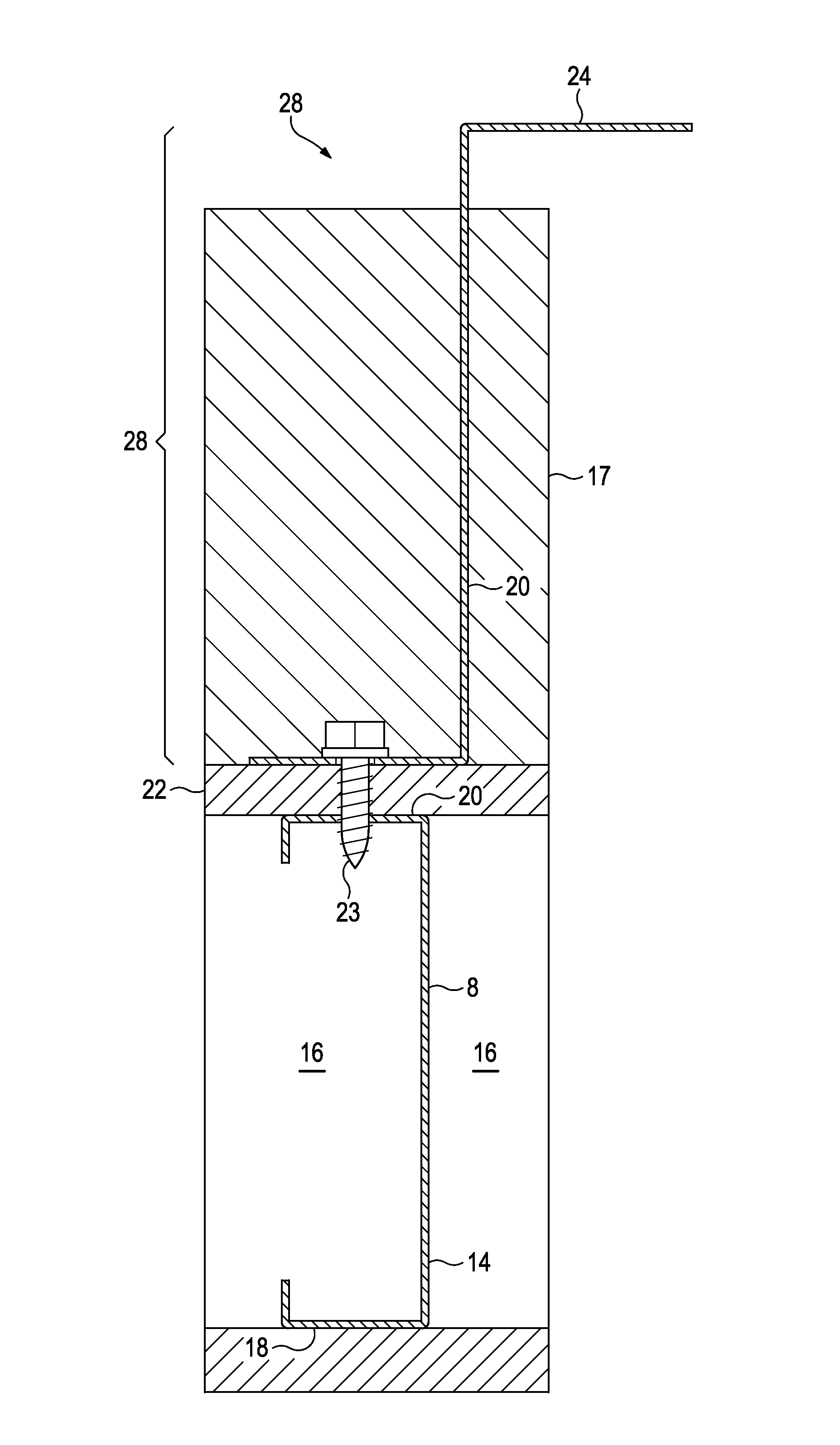
[0041]As shown in FIG. 1, a wall structure is commonly formed of vertical wall studs 8 that are spaced apart from each other and attached to a wall plate (not shown) at one end and a ceiling plate (not shown) at the other end. The studs form cavities 16 between them, and are commonly formed from steel. They are rigidly interconnected to both the wall plate and the ceiling plate, forming a support structure 14. The support structure 14 has an opposing inside facing aspect 18 and an outside facing aspect 20, corresponding to the building interior facing aspect of the wall and the building exterior facing aspect of the wall. Adjoining walls form corners with various angles, and window openings and door openings are commonly defined.

[0042]The elements of the building envelope are attached to the support structure 14. Conventionally, sheathing 22 such as plywood, oriented strand board, or exterior grade gypsum board may be attached to the outside facing aspect 20 of the support structure...


PUM

PropertyMeasurementUnit
Surface areaaaaaaaaaaa
Energyaaaaaaaaaa
aaaaaaaaaa

Abstract

An isolator system for preventing the conduction of thermal energy between the metal components of a wall assembly comprising isolator plates adapted to be placed between the metal components of a wall assembly and made of an insulating material. The isolator plates include at least one opening for receiving a fastener, said opening has an annular shoulder adapted to extend into an opening for receiving said fastener in a metal component of a wall assembly. Also disclosed herein is a thermal isolation washer and a girt for use with polymer panel construction.

Description

CROSS-REFERENCE TO RELATED APPLICATIONS[0001]This application is a continuation-in-part of and claims priority from U.S. patent application Ser. No. 12 / 928,151, filed Dec. 6, 2010, which is incorporated by reference as if fully set forth herein.BACKGROUND OF THE INVENTION[0002]The construction, maintenance, and habitation of buildings is the single biggest contributor of greenhouse gases, and heating and cooling systems account for up to 50% of energy used in buildings in the United States. Reducing the energy used to heat and cool buildings is critical to energy conservation, and energy conservation is critical to both national security and economic prosperity.[0003]A variety of governmental and non-governmental organizations are causing a tightening of energy efficiency standards as they pertain to buildings. In 1992, Congress passed the Energy Policy Act which required states to have building codes that set efficiency standards that are at least as stringent as the Federal standa...

Claims


Application Information

Patent Timeline
IPC IPC(8): E04B2/56E04B1/80E04B1/76
CPCE04B2/562E04B1/76E04B1/80E04F13/0733E04F13/0862E04F13/12E04B2001/2481B32B2607/00E04B1/94E04B1/762E04B2/7412F16B43/001E04F13/14E04F13/0805E04B1/388E04B1/7629E04B1/7637E04B2/58E04B2001/7679E04B2103/04E04B2103/06E04F13/0875E04B1/7604E04B1/7608
Inventor CROASDALE, SCOTT
Owner KNIGHT WALL SYST
Why Eureka
Try Eureka