
Photovoltaic generation system using parallel inverter connected grid

a photovoltaic generation and parallel inverter technology, applied in the direction of dc-ac conversion without reversal, dc network circuit arrangement, semiconductor devices, etc., can solve the problems of high unit price, leakage current through ground, and difficulty in design, so as to reduce stray current

Inactive Publication Date: 2013-03-28
KACO NEW ENERGY INC
View PDF4 Cites 19 Cited by
  • Summary
  • Abstract
  • Description
  • Claims
  • Application Information

AI Technical Summary

Benefits of technology

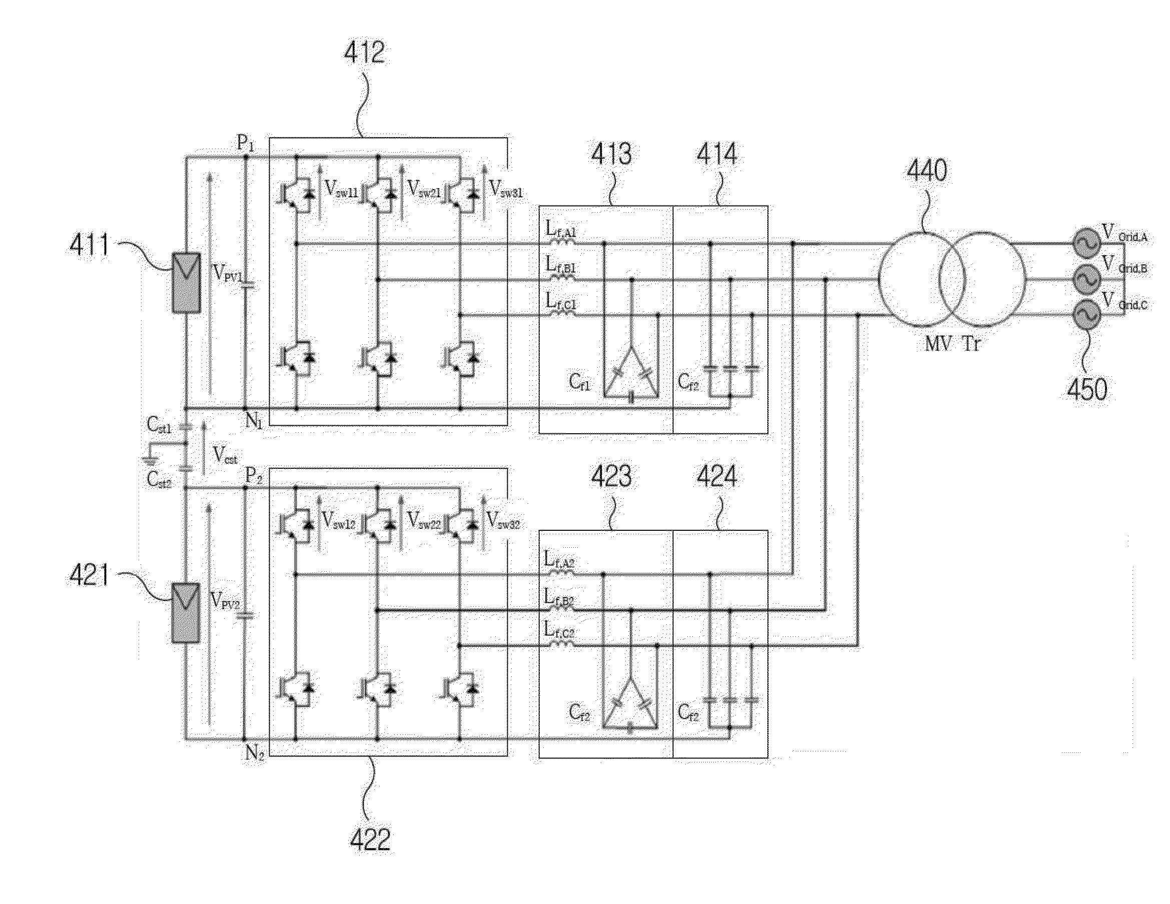
The present invention aims to solve problems in the related art by providing a photovoltaic generation system using grid-connected parallel inverters that can significantly reduce stray current, deterioration of photovoltaic modules due to stray current, harmonic distortion in output waveform, and the use of a double wiring transformer instead of a multi-wiring transformer.

Problems solved by technology

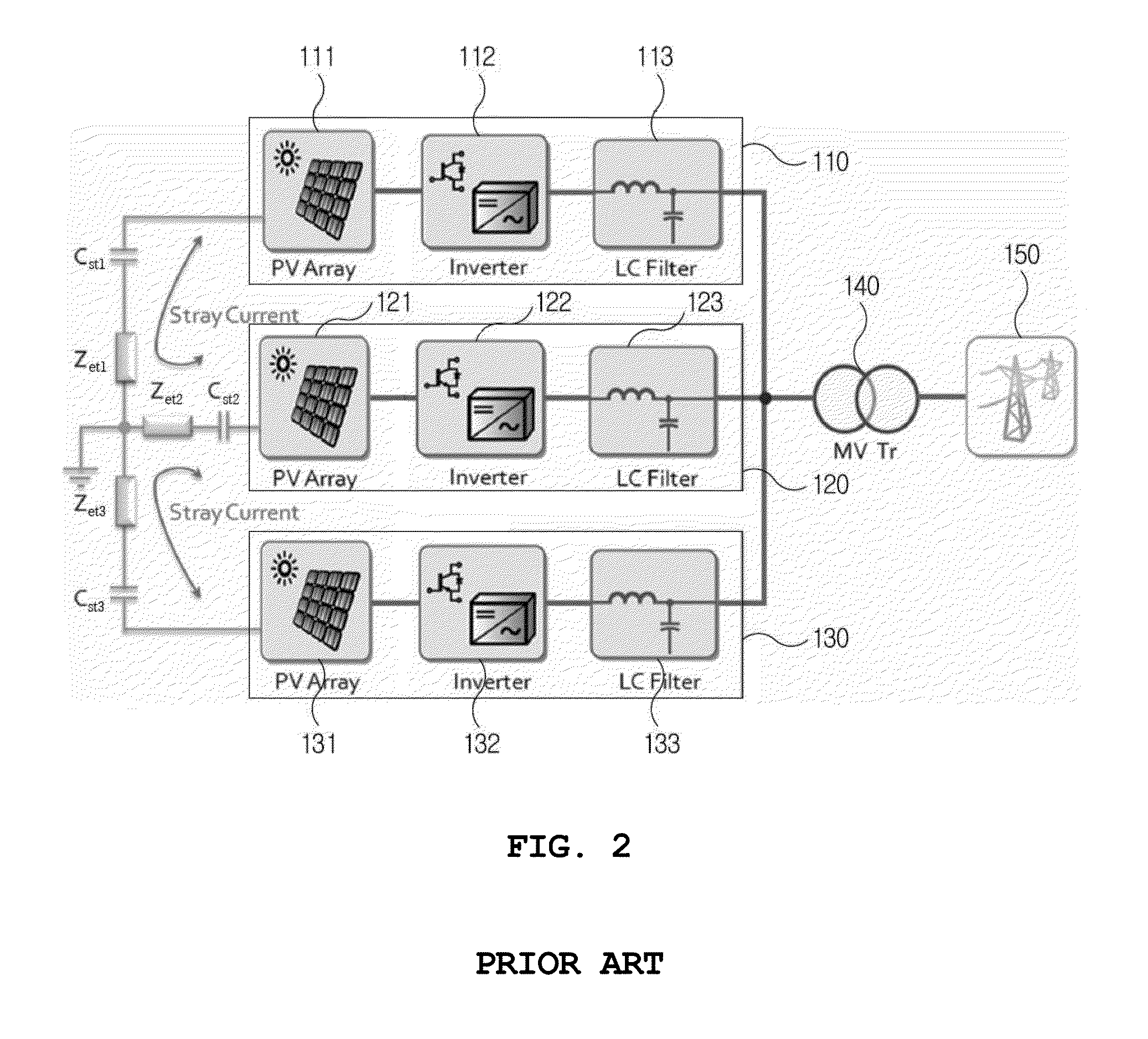
When a voltage of a harmonic component occurs at the stray capacitance, leakage current occurs through the ground, and several problems are accompanied.
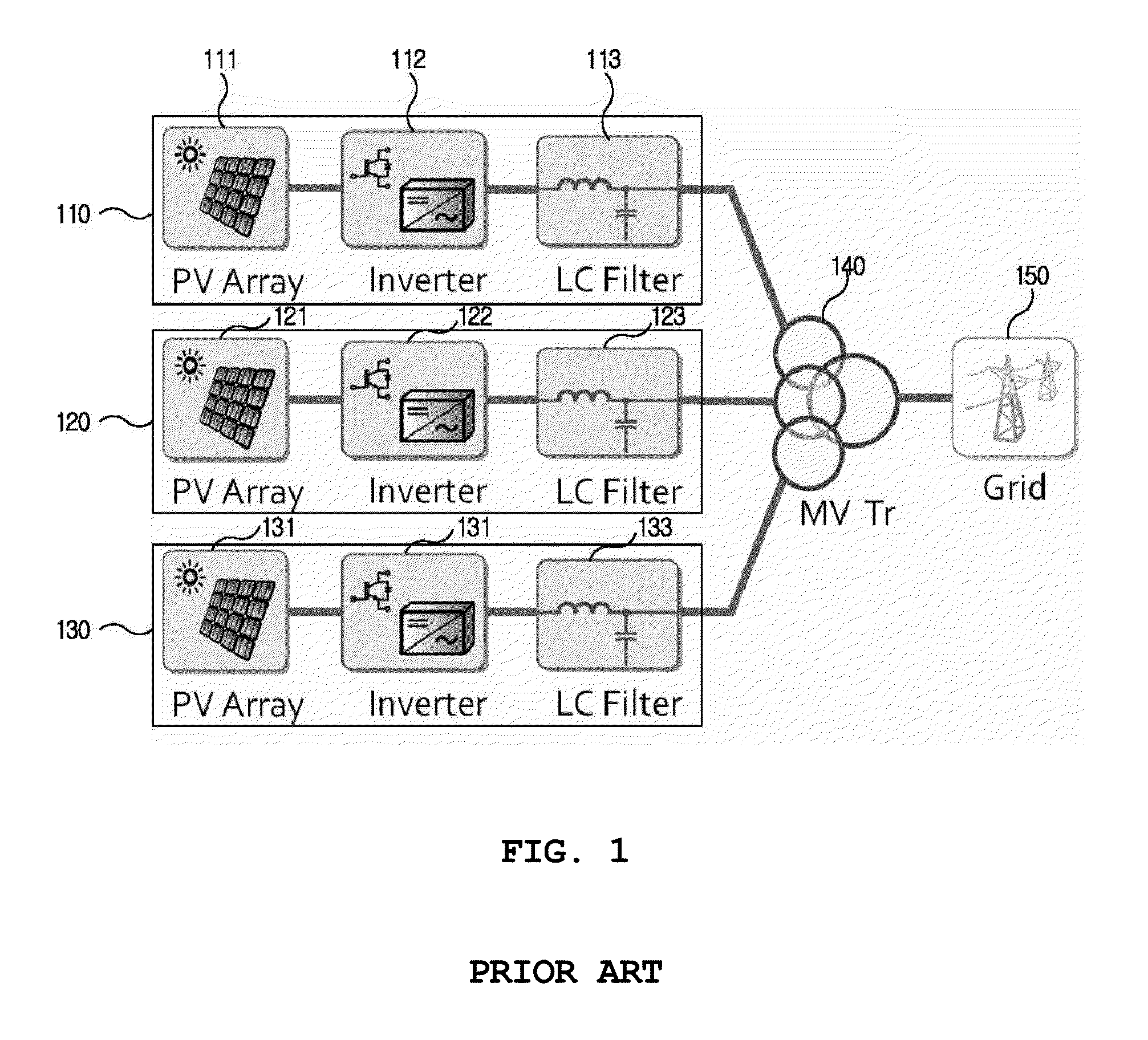
Therefore, as shown in FIG. 1, the conventional parallel photovoltaic inverters are using multi-wiring MV transformers for electrical separation between inverters and isolation of a grid from inverters although a high unit price, a difficulty in design, and inefficiency are recognized.
As described above, the conventional photovoltaic generation system using a double wiring transformer causes undesired stray current, so that there is a danger of an electrical shock when the worker touches a photovoltaic module, the photovoltaic module is easily deteriorated and is easily broken due to the deterioration thereof, and high harmonic distortion appears in the output waveform of the inverter.

Method used


Image

  • Photovoltaic generation system using parallel inverter connected grid
  • Photovoltaic generation system using parallel inverter connected grid
  • Photovoltaic generation system using parallel inverter connected grid

Examples


Embodiment Construction

[0040]Reference will now be made in greater detail to a preferred embodiment of the invention, an example of which is illustrated in the accompanying drawings. Wherever possible, the same reference numerals will be used throughout the drawings and the description to refer to the same or like parts. In the below description, many particular items are shown, but these are given only for providing the general understanding of the present invention. It will be understood by those skilled in the art that the present invention can be embodied without these particular items. In addition, in the following description, a detailed description of known functions and configurations incorporated herein will be omitted when it may obscure the subject matter of the present invention.

[0041]FIG. 5 is a circuit diagram of a photovoltaic generation system using grid-connected parallel inverters according to an embodiment of the present invention, FIG. 6 is an equivalent circuit of FIG. 5, and FIG. 7 i...


PUM


Abstract

A photovoltaic generation system using grid-connected parallel inverters comprises a plurality of photovoltaic generation devices connected in parallel with each other, and a transformer configured to transform and transfer output voltages of the photovoltaic generation devices to a grid, wherein the photovoltaic generation device includes: a photovoltaic module configured to convert photovoltaic energy into DC electrical energy; an inverter configured to convert the DC electrical energy outputted from the photovoltaic module into AC electrical energy; an LC filter configured to remove noise included in the AC electrical energy which is outputted from the inverter; and a Y-connected capacitor group which is connected between one terminal of a reactor in the LC filter and one terminal of the photovoltaic module and is configured to reduce stray current.

Description

CROSS-REFERENCE TO RELATED APPLICATION[0001]The present application claims the benefit under 35 U.S.C. §119(a) to a Korean patent application No. 10-2011-0097363, filed on Sep. 27, 2011, and the disclosure of which is expressly incorporated by reference in its entirety.BACKGROUND OF THE INVENTION[0002]1. Field of the Invention[0003]The present invention relates to a photovoltaic generation system, and more particularly, to a photovoltaic generation system using grid-connected parallel inverters.[0004]2. Description of the Related Art[0005]It has been determined that fossil energy, such as oil, coal, and natural gas, is available for 30 years in case of oil, 80 years in case of coal, and 180 in case of natural gas. Due to the United Nations Framework Convention on Climate Change (UNFCCC), such as the Kyoto protocol, and so on, new and renewable energy has received an increasing amount of attention. The new energy field includes a fuel cell, coal liquefaction / gasification, and hydroge...

Claims


Application Information

Patent Timeline
IPC IPC(8): H02M7/5387
CPCH02M1/126H02M7/493H01L31/02021H02J3/383Y02E10/563H02M2001/123H02J2300/24H02J3/381Y02E10/56H02M1/123H02J7/35H02M7/48H02M1/12
Inventor BAE, YOUNG SANGOH, SEONG JINKIM, KYOUNG HWAN
Owner KACO NEW ENERGY INC
Learn More