Removal of mercury emissions

a technology for mercury emissions and removal, applied in the field of apparatus and methods, can solve the problems of reducing the efficiency of sorbents, so as to achieve cost-effective effects

Active Publication Date: 2013-03-28
GENERAL ELECTRIC TECH GMBH
View PDF3 Cites 34 Cited by
  • Summary
  • Abstract
  • Description
  • Claims
  • Application Information

AI Technical Summary

Benefits of technology

[0023]An object of the present invention is to provide a more efficient method of removing gaseous pollutants from flue gases.
[0024]Another object of the present invention is to provide a more efficient method of removing mercury and mercury compounds from flue ga...

Problems solved by technology

Both of these differences make it more difficult to remove the mercury from the flue gas from a coal-fired power plant.
The efficiency of the sorbent is limited by its surface area to mass ratio.
A relatively large particle has a low available surface area/mass ratio that limits the adsorption of pollutant gas.
Using a carbonaceous sorbent with mean particle ...

Method used


Image

  • Removal of mercury emissions
  • Removal of mercury emissions
  • Removal of mercury emissions

Examples


Embodiment Construction

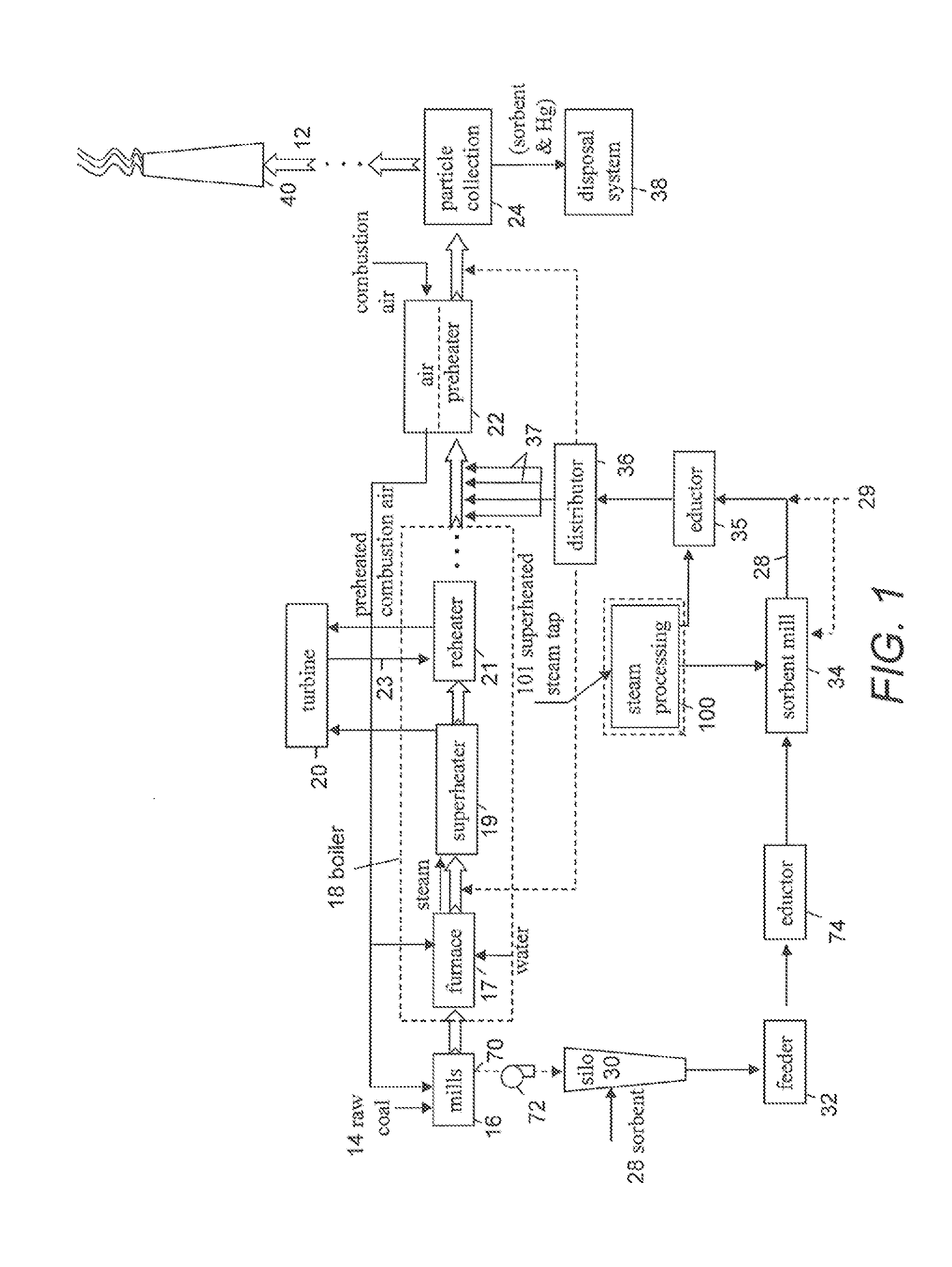
[0031]FIG. 1 shows an embodiment of the present invention incorporated into a solid fuel fired steam generator or boiler 18. This may be part of a coal-fired power plant.

[0032]The raw coal 14 is fed to at least one pulverizer / crusher, each referred to as a mill 16 where the raw coal is reduced to desired particulate size. Ambient air is provided to an air preheater 22 that preheats the air. The preheated air is provided as primary air to the mills 16 that carries the solid fuel particles that were pulverized in mills 16, to the furnace 17 of boiler 18, where the fuel particles are burned to boil water into steam.

[0033]Air preheater 22 also provides secondary air directly to furnace 17.

[0034]The temperature of the flue gases leaving the furnace 17 ranges from 1400 to 2200° F.

[0035]The steam created in the furnace 17 is provided to superheater 19. The hot flue gases are also provided to superheater 19. The superheater transfers heat from the flue gases to the steam creating superheate...


PUM

PropertyMeasurementUnit
Temperatureaaaaaaaaaa

Abstract

A system for removing gaseous pollutants, such as mercury from flue gases of a solid-fueled furnace (17), includes a sorbent mill (34) that receives superheated steam and a sorbent (28), such as activated carbon, in a partially agglomerated state, that processes the sorbent (28) by de-agglomerating and comminuting the sorbent (28). An educator (35) transports the processed sorbent (28) to a distributor (36) that injects it into the flue gases at a contact location having a temperature between 500° F. and 900° F., whereupon the sorbent (28) adsorbs mercury from the flue gas. A particle collection device (24) removes the processed sorbent (28) having adsorbed mercury, from the flue gas.

Description

CROSS-REFERENCE TO RELATED APPLICATIONS[0001]The present application claims priority from U.S. Provisional Patent Application Ser. No. 61 / 538,475, filed Sep. 23, 2011. The present application is also related to U.S. Pat. No. 7,780,765 issued Aug. 24, 2010 that was a continuation of U.S. patent application Ser. No. 10 / 961,697, filed Oct. 8, 2004, which is a continuation-in-part of U.S. patent application Ser. No. 10 / 453,140, filed Jun. 3, 2003, now U.S. Pat. No. 6,848,374, all of which are incorporated by reference as if they were set forth in their entirety herein.BACKGROUND OF THE INVENTION[0002]The present invention relates to apparatus and a method for removing gaseous pollutants from the flue gas of solid fuel fired steam generators and more particularly to apparatus and a method for removing elemental mercury and mercury compounds from the flue gases from coal fired boilers.[0003]The use of activated carbon and carbonaceous particles for the adsorption of pollutant gases, such ...

Claims


Application Information

Patent Timeline
IPC IPC(8): B01D53/12
CPCB01D53/12B01D53/08B01D53/64B01D53/83F23J2219/30B01D2257/602F23J15/02F23J2215/60B01D2253/102B01D53/10
Inventor LAFLESH, RICHARD C.IOVINO, JOHNKANG, SHIN GYOOEDBERG, CARL DCOURNOYER, RAYMOND W.
Owner GENERAL ELECTRIC TECH GMBH
Why Eureka
Try Eureka