
Dosing pump system

a pump system and pump technology, applied in the direction of machines/engines, liquid fuel engines, positive displacement liquid engines, etc., can solve the problems of limiting the performance capabilities of the dosing pump system to a narrow range of operation, complex and expensive systems of the precise dosing pump system, and limiting the performance capabilities of the dosing pump system. achieve the effect of reducing or eliminating, widening the operation flow range and maintaining the level of accuracy and precision

Active Publication Date: 2013-04-04
MICRO INFINITY FLOW LLC
View PDF5 Cites 7 Cited by
  • Summary
  • Abstract
  • Description
  • Claims
  • Application Information

AI Technical Summary

Benefits of technology

The present invention provides a compact and versatile dosing pump system that can deliver fluid in both small and large amounts without the need for additional components like sensors and flow meters. The system uses a network of fluid paths and valves to route fluid through the pump, making it highly precise and accurate even when using pumps with varying precision. The dosing pump system can control both microdose and macrodose flow rates, and may be enhanced by a control system that monitors and adjusts the pump's operation. This eliminates the need for additional sensors and reduces the overall cost and size of the dosing pump system.

Problems solved by technology

Precise dosing pump systems are complex and expensive systems, are highly specialized, and are limited to particular applications.
The highly specialized nature of dosing pumps systems limits their performance capabilities to a narrow range of operation.
Furthermore, due to their high cost, dosing pump systems are typically limited to high-end applications in fields such as medical and industrial, while commercial and consumer applications have limited access to the technology.
Regardless of the pump technology, however, dosing pumps are typically designed for and limited to providing very low flow rates such as 0.01 millileters per minute to 5 milliliters per minute.
flow rate, however, is that dosing pump systems have a limited range of adjustability such that they are not effective to operate outside of the nominal design flow rate.
Use of a higher flow rate dosing pump, such as a pump that operates in a range of 20 milliliters per minute to 50 milliliters per minute, in order to expand the range of flow rates is typically not an option because the increased flow rate comes at the loss of accuracy and precision.
Therefore, dosing pumps capable of precisely controlling macrodose flow are expensive and highly uncommon.
Both precise microdose pumps as well as macrodose pumps tend to be expensive.
Also increasing the cost is the need of certain applications that require both microdosing and macrodosing because more than one pump is required to achieve all of the desired dosing ranges.
Current dosing pumps lack the necessary degree of adjustability to cover large ranges of flow rate.
Further drawbacks of prior dosing pump systems are the variety of devices in addition to the pump that are required in order to monitor and control the flow of fluid.
These additional components contribute to the complexity and cost of the system, as well as add physical bulk.
The sensitivity of readily available flow sensors, such as turbine sensors, is also not sufficient for accurately determining the flow rate of fluids at microdosing levels, generally within the range of 0.01 millileters per minute to 5 milliliters per minute.
In the case of traditional turbine sensor, the microdose flow rate cannot adequately spin the turbine to generate sufficient signal to determine the actual flow rate of the fluid.
Thus, In a traditional microdosing system, such flow sensors cannot be utilized because the pump operates to draw in and expel fluid at essentially the same microdosing rate resulting in an input flow and an output flow that are each at microdosing levels.
Microdosing sensors have significant drawbacks such as a high cost, generally thousands of dollars.
The design of the particular dosing system is thus limited to a particular flow rate for a particular fluid viscosity.
However, this is achievable only within a narrow operational range and through the assembly of a complex and expensive flow control system.

Method used


Image

  • Dosing pump system
  • Dosing pump system
  • Dosing pump system

Examples


Embodiment Construction

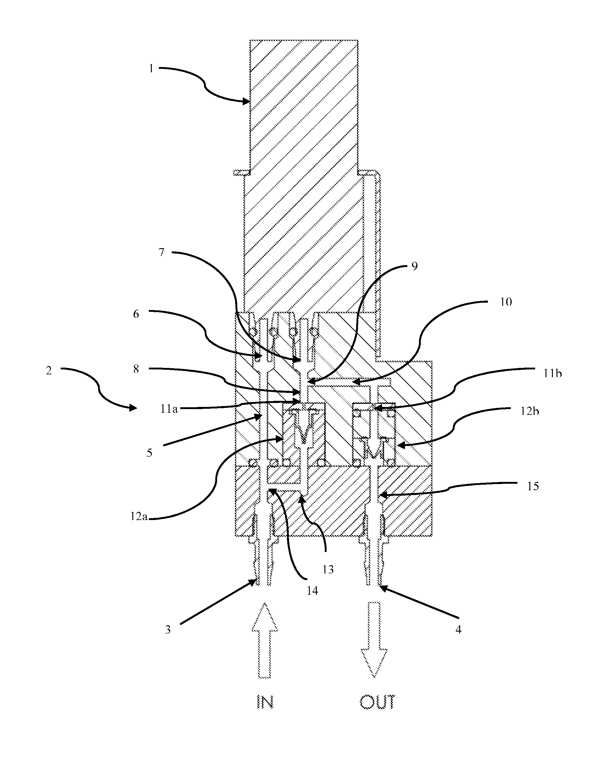
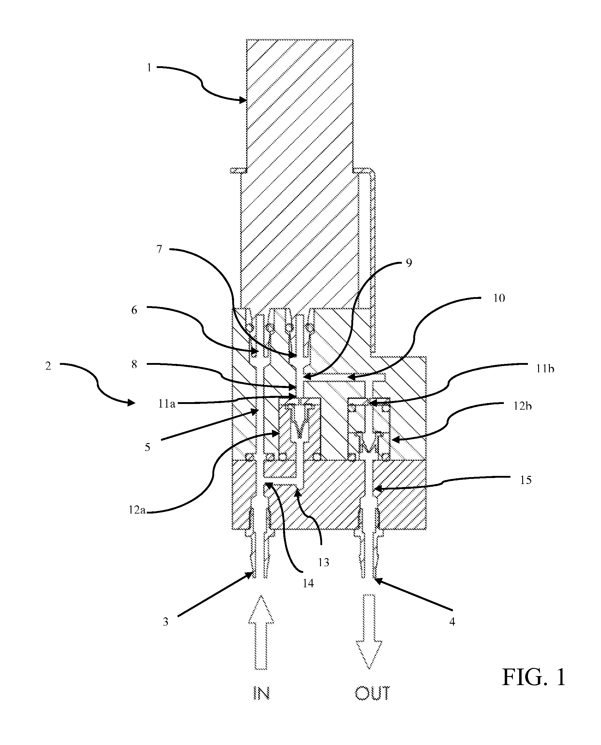
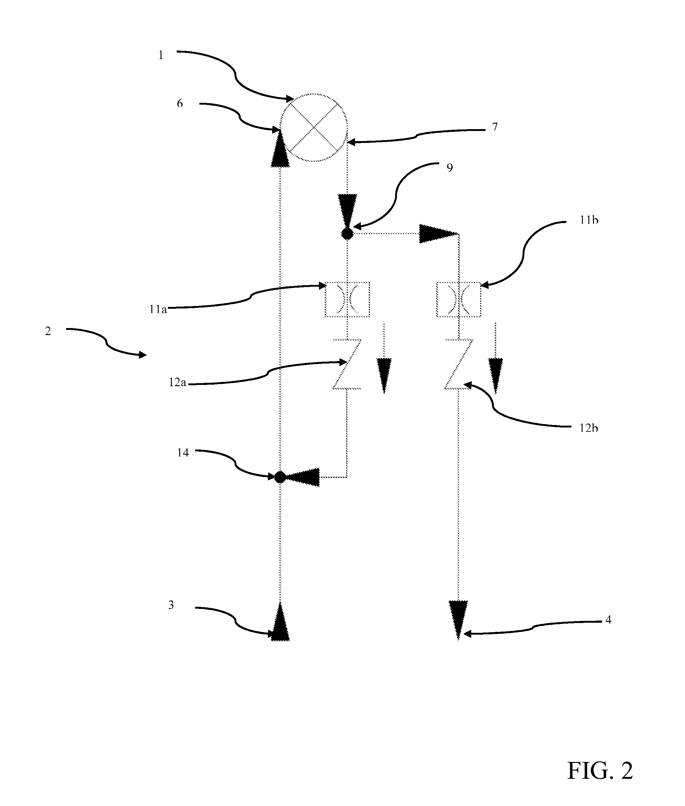
[0021]The preferred embodiments of the present invention are described with reference to the drawings below. In the drawings, like numbers are used to refer to like elements. The construction of the dosing pump is comprised of two primary subsystems: a fluid pump and a flow circuit. A controller, which may be, and preferably is, a microprocessor based control system, may also be utilized to provide closed loop feedback control of the dosing pump system. The pump, flow circuit, and control system are assembled into a compact, modular dosing pump system. The dosing pump system includes a fluid inlet port to couple to a fluid source and a fluid outlet port to discharge the fluid; no flow control devices are required external to the dosing pump system.

[0022]Referring to FIG. 1, the fluid pump 1 is assembled to, and in fluid communication with, the flow circuit, generally identified as 2. The fluid pump 1 provides a pressure differential to move fluid through the system. The flow circuit...


PUM


Abstract

A compact, modular dosing pump system that is capable of microdose and macrodose volume flow rates, reduces or eliminates the need for additional flow control components such as temperature and pressure sensors, and utilizes a wider operational flow range than existing systems while maintaining the level of accuracy and precision exhibited by conventional dosing pump systems is provided. The dosing pump utilizes a pump and flow circuit, and a control system may be used to deliver a range of fluid volumes. The flow circuit utilizes a networked system of fluid paths and valves to route fluid through the dosing pump system in response to a pressure differential between fluid inlet and fluid outlet ports, while the controller monitors and controls the operation of the system.

Description

CROSS-REFERENCE TO RELATED APPLICATION:[0001]This application claims priority to U.S. Provisional Application Ser. No. 61 / 542628 filed Oct. 3, 2011, the entirety of which is incorporated herein by this reference.FEDERALLY SPONSORED RESEARCH OR DEVELOPMENT [0002]Not Applicable.BACKGROUND OF THE INVENTION[0003]The present invention generally relates to devices capable of delivering precisely metered fluid volumes. Specifically, the invention includes a pump that may provide both a microdose and macrodose so as to accurately deliver a precise volume of fluid with high resolution adjustment over a wide range of microdose and macrodose volumes. The invention can be configured for use in fields which include medical, pharmaceutical, food and beverage, industrial process, laboratory, and chemical, as well as commercial and consumer applications.[0004]Precise dosing pump systems are complex and expensive systems, are highly specialized, and are limited to particular applications. The highly...

Claims


Application Information

Patent Timeline
Patent Type & Authority Applications(United States)
IPC IPC(8): E03B11/16
CPCG01F1/34F04B53/16F04B13/00Y10T137/85978F04B43/04F04B49/225F04B49/20F04B49/24F04B53/10F04C2/344F04C14/08F04C14/26F04C15/008F04D13/06F04D15/0011F04D15/0066F04D29/18
Inventor UBIDIA, FERNANDO
Owner MICRO INFINITY FLOW LLC
Learn More