Narrow gauge high strength choked wet tip microwave ablation antenna

a wet tip, microwave ablation technology, applied in the field of microwave ablation surgical probes, can solve the problems of increasing the likelihood of complications, putting undue stress on the probe, and routine observation of thermal damage to most types of normal cells, so as to improve power delivery performance and power handling, the effect of reducing the temperature of the componen

Active Publication Date: 2013-04-04
COVIDIEN LP
View PDF2 Cites 15 Cited by
  • Summary
  • Abstract
  • Description
  • Claims
  • Application Information

AI Technical Summary

Benefits of technology

This patent describes an electromagnetic surgical ablation probe with a cooled and dielectrically buffered antenna assembly. The probe uses a coaxial conductor to provide electromagnetic energy and a fluid conduit for coolant. The probe has a metal or plastic tip, which can be easily inserted into tissue. The probe has a dipole structure and a cylindrical radiating section that extends further distally towards the tip. The technology has advantages such as achieving a large ablation diameter, a nearly spherical ablation shape, low reflected power, cool probe shaft, narrow gauge needle size for percutaneous procedures, increased strength and stiffness, and balun short to reduce complications from multiple antenna interactions.

Problems solved by technology

However, at slightly elevated temperatures above the approximate range of 43° C. to 45° C., thermal damage to most types of normal cells is routinely observed.
During such a procedure, negotiating the probe through, for example, fibrous thoracic tissue and ribs may place undue stresses on the probe.
Additionally, microwave energy may radiate into the skin, which may increase the likelihood of complications, such as skin burn.
The balun short may confine most radiation to the distal tip of the probe, reducing the likelihood of complications from multiple antenna interactions, which may cause skin burn

Method used


Image

  • Narrow gauge high strength choked wet tip microwave ablation antenna
  • Narrow gauge high strength choked wet tip microwave ablation antenna
  • Narrow gauge high strength choked wet tip microwave ablation antenna

Examples


Embodiment Construction

[0027]Particular embodiments of the present disclosure will be described hereinbelow with reference to the accompanying drawings; however, it is to be understood that the disclosed embodiments are merely exemplary of the disclosure, which may be embodied in various forms. Well-known functions or constructions are not described in detail to avoid obscuring the present disclosure in unnecessary detail. Therefore, specific structural and functional details disclosed herein are not to be interpreted as limiting, but merely as a basis for the claims and as a representative basis for teaching one skilled in the art to variously employ the present disclosure in virtually any appropriately detailed structure.

[0028]In the drawings and in the descriptions that follow, the term “proximal,” as is traditional, shall refer to the end of the instrument that is closer to the user, while the term “distal” shall refer to the end that is farther from the user.

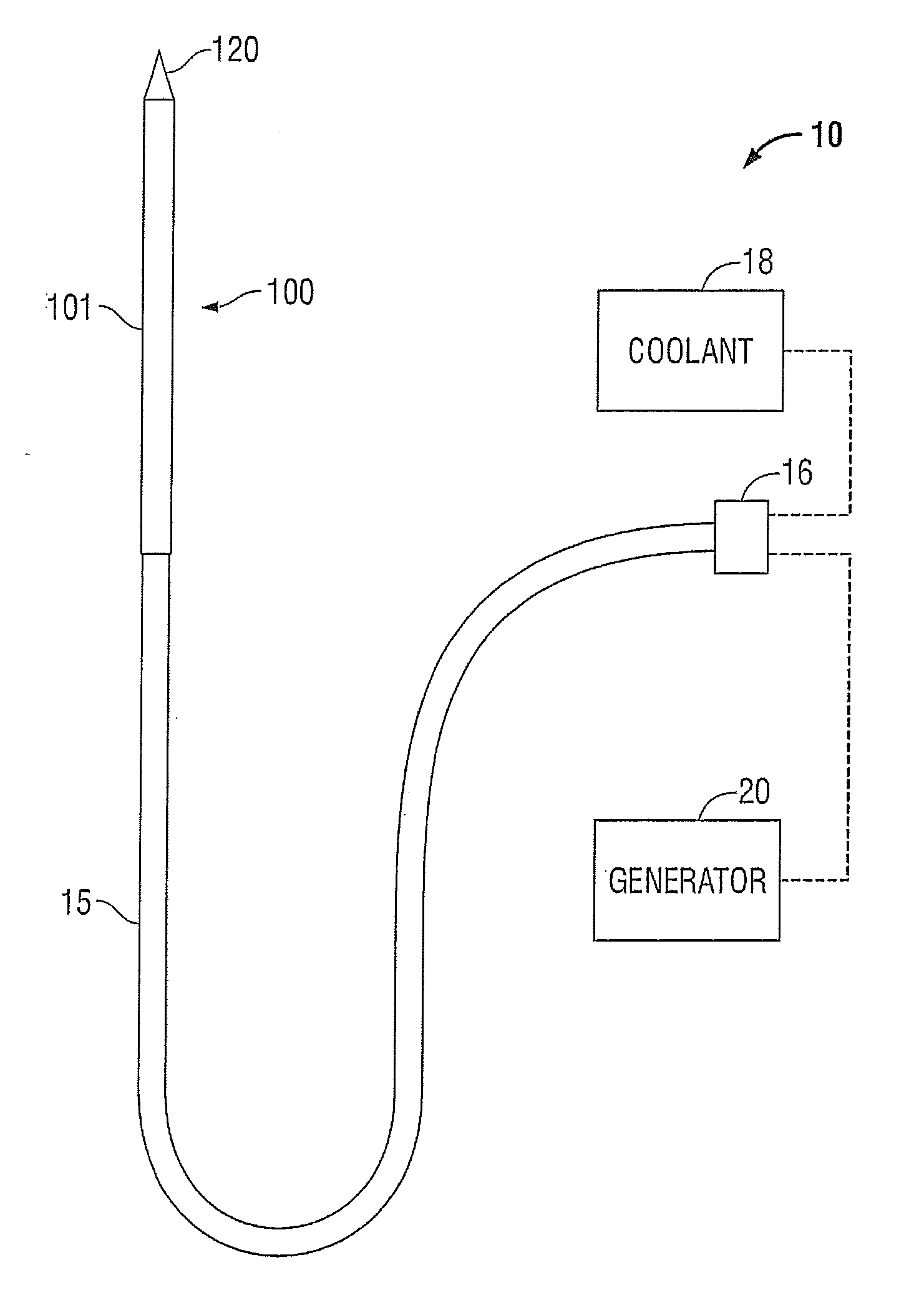
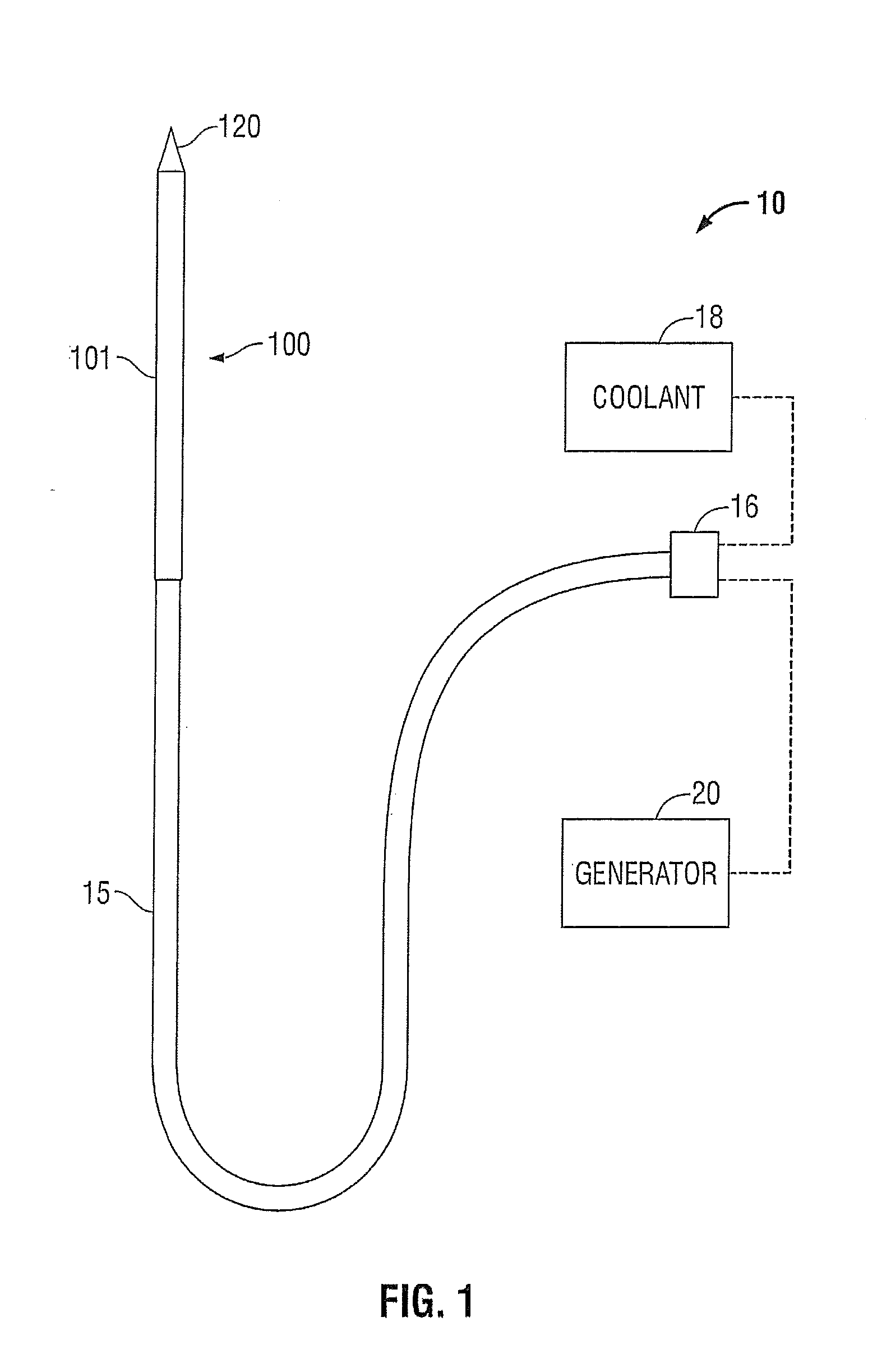
[0029]FIG. 1 shows an embodiment of a micr...


PUM


Abstract

An electromagnetic surgical ablation probe having a coaxial feedline and cooling chamber is disclosed. The disclosed probe includes a dipole antenna arrangement having a radiating section, a distal tip coupled to a distal end of the radiating section, and a ring-like balun short, or choke, which may control a radiation pattern of the probe. A conductive tube disposed coaxially around the balun short includes at least one fluid conduit which provides coolant, such as dionized water, to a cooling chamber defined within the probe. A radiofrequency transparent catheter forms an outer surface of the probe and may include a lubricious coating.

Description

CROSS-REFERENCE TO RELATED APPLICATION[0001]This application is a Continuation of U.S. patent application Ser. No. 12 / 472,831, filed May 27, 2009, now U.S. Pat. No. 8,292,881, the entirety of which is hereby incorporated by reference herein for all purposes.BACKGROUND[0002]1. Technical Field[0003]The present disclosure relates to systems and methods for providing energy to biological tissue and, more particularly, to a microwave ablation surgical probe having a concentric tubular structure and conical distal tip, and methods of use and manufacture therefor.[0004]2. Background of Related Art[0005]Energy-based tissue treatment is well known in the art. Various types of energy (e.g., electrical, ultrasonic, microwave, cryogenic, thermal, laser, etc.) are applied to tissue to achieve a desired result. Microwave energy can be delivered to tissue using an antenna probe. Presently, there are several types of microwave probes in use, e.g., monopole, dipole, and helical. One type is a monopo...

Claims


Application Information

Patent Timeline
Patent Type & Authority Applications(United States)
IPC IPC(8): A61B18/18A61B18/14
CPCA61B18/18A61B18/1815Y10T29/49117A61B18/14A61B2018/00023A61B2018/1869A61B2018/00577A61B2018/1823
Inventor BRANNAN, JOSEPH D.BONN, KENLYN S.
Owner COVIDIEN LP
Why Eureka
Try Eureka