Combustion system

a combustion system and combustion technology, applied in the field of combustion systems, can solve the problems of high carbon content of coal fuel, achieve the effects of reducing the flow rate of exhaust gas, and reducing the capacity of the smoke removal devi

Inactive Publication Date: 2013-04-18
MITSUBISHI HITACHIPOWER SYST LTD
View PDF5 Cites 4 Cited by
  • Summary
  • Abstract
  • Description
  • Claims
  • Application Information

AI Technical Summary

Benefits of technology

[0028]In the present invention, part of exhaust gas diverging from between the combustion furnace and the smoke removal device is resupplied to the inside of the combustion furnace through the burner unit. A zone under reducing atmosphere is formed between the burner unit of the combustion furnace and the combustion oxygen supply port. Consequently, the exhaust gas diverging from between the combustion furnace and the smoke removal device can be reduced in the zone under reducing atmosphere formed in the combustion furnace before being discharged. This makes it possible to decrease the flow rate of the exhaust gas introduced from the combustion furnace to the smoke removal device and to decrease the flow rate of smoke. Therefore, the capacity of the smoke removal device can be reduced.
[0029]Moreover, part of exhaust gas diverging from the downstream side of the smoke removal device is the exhaust gas having the concentration of nitrogen oxide, which is smoke, decreased by the smoke removal device. The exhaust gas having a decreased nitrogen oxide concentration is introduced to the combustion oxygen supply port and is used for promoting complete combustion of the unburned fuel contained in the exhaust gas which has partially been reduced by passing the reducing atmosphere inside the combustion furnace. Therefore, the exhaust gas can be discharged out of the combustion furnace while the concentration of nitrogen oxide contained therein is maintained low. The exhaust gas having a decreased nitrogen oxide concentration is recirculated to the combustion furnace and the smoke removal device, so that increase in the concentration of nitrogen oxide in the outlet of the combustion furnace can be suppressed.

Problems solved by technology

However, coal is high in carbon contents in fuel compared with oil and gas.

Method used


Image

  • Combustion system
  • Combustion system
  • Combustion system

Examples


first embodiment

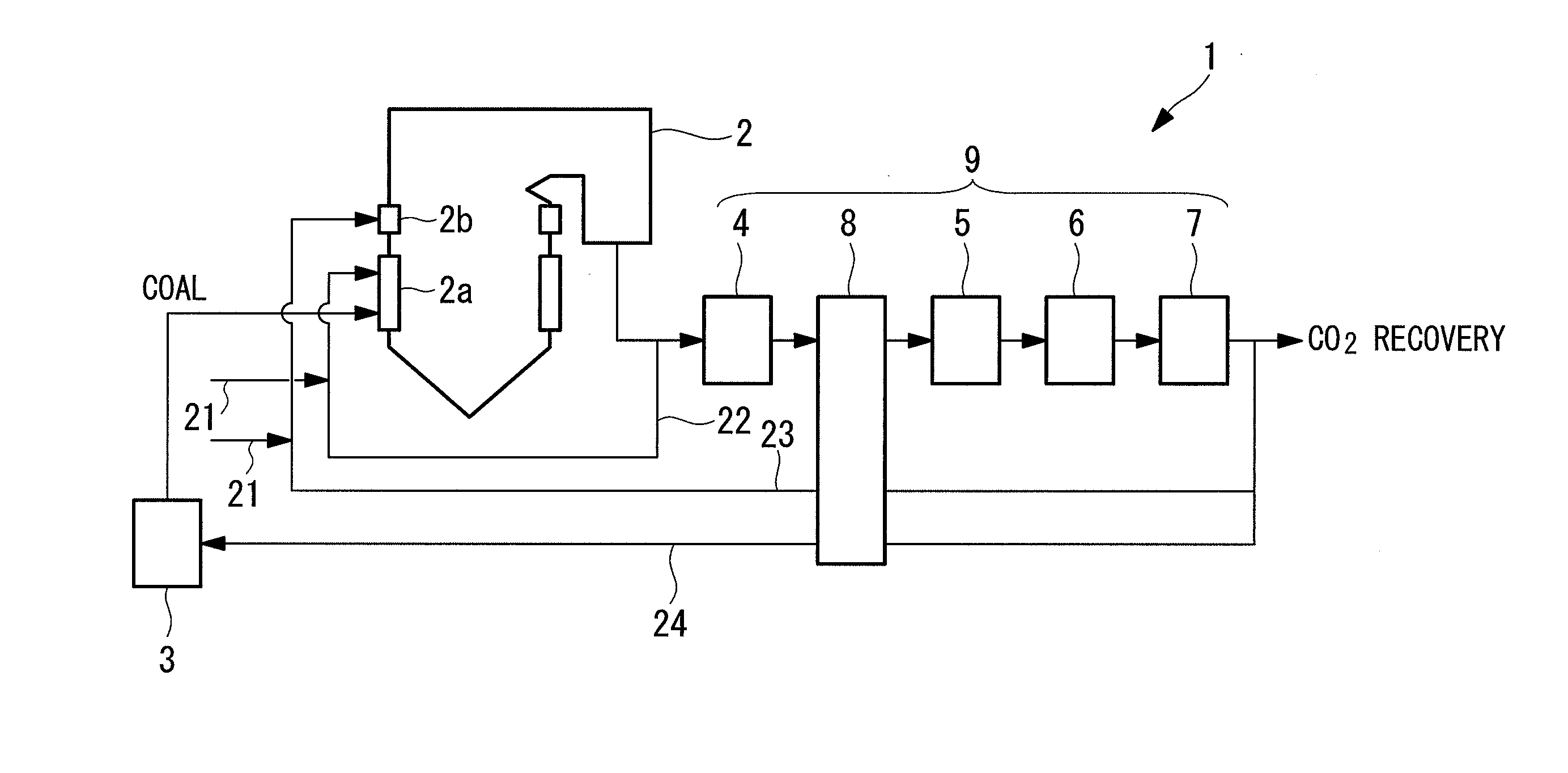
[0035]FIG. 1 is a schematic structure view of a combustion system according to the first embodiment of the present invention.

[0036]The combustion system 1 includes a coal fired boiler (combustion furnace) 2, a coal pulverizer 3 for pulverizing coal supplied to the coal fired boiler 2, and a smoke removal device 9.

[0037]The coal fired boiler 2 is an oxygen combustion boiler which can conduct denitration inside the furnace (not shown) by two-stage combustion. The coal fired boiler 2 includes a furnace inside for combusting fuel, a burner unit 2a, and an additional air port (hereinafter referred to as “AA unit”) 2b. Coal as fuel supplied from the coal pulverizer 3, oxygen (combustion oxygen) introduced from a combustion oxygen supply system 21, and later-described secondary recirculation gas for burner unit 22 are introduced to the burner unit 2a. Remaining part of the oxygen introduced from the combustion oxygen supply system 21 to the burner unit 2a and later-described secondary reci...

second embodiment

[0061]Hereinafter, the second embodiment of the present invention will be described. A combustion system of the present embodiment is different from the first embodiment in the point that the secondary recirculation gas for AA unit is introduced from between the desulfurization device and the gas cooler. Other structural members are similar to those of the first embodiment. Therefore, like structural members and flows are designated by like reference signs to omit description.

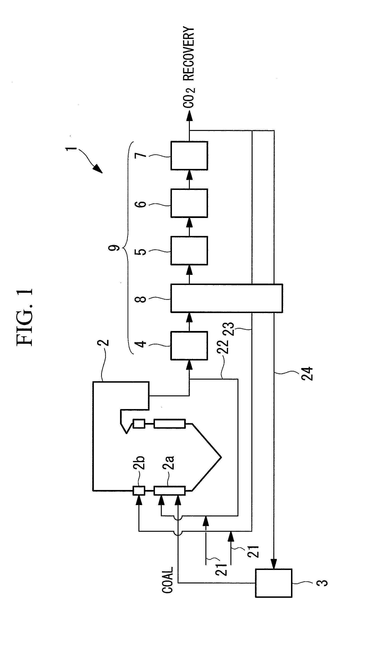
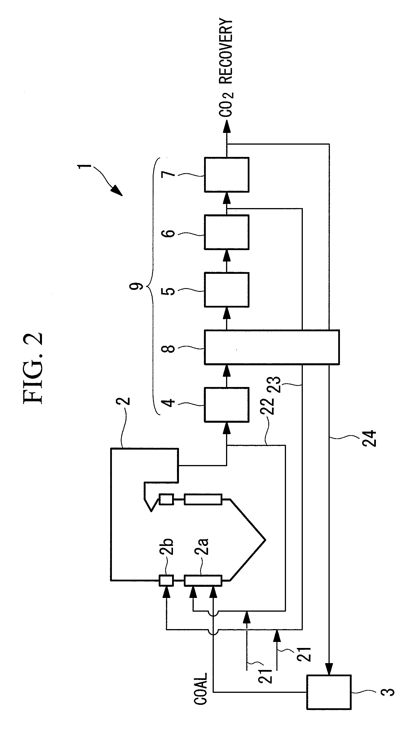
[0062]FIG. 2 is a schematic structure view of a combustion system according to the second embodiment of the present invention.

[0063]Oxygen (combustion oxygen) introduced from a combustion oxygen supply system 21 and part of exhaust gas diverging from between a desulfurization device (desulfurization unit) 6 and a gas cooler (cooling unit) 7 which constitute a smoke removal device 9 are supplied to an AA unit (combustion oxygen supply port) 2b of a coal fired boiler (combustion furnace) 2 as secondary recirculat...

third embodiment

[0066]Hereinafter, the third embodiment of the present invention will be described. A combustion system of the present embodiment is different from the first embodiment in the point that the secondary recirculation gas for AA unit is introduced from between the dust removal device and the desulfurization device. Other structural members are similar to those of the first embodiment. Therefore, like structural members and flows are designated by like reference signs to omit description.

[0067]FIG. 3 is a schematic structure view of a combustion system according to the third embodiment of the present invention.

[0068]Oxygen (combustion oxygen) introduced from a combustion oxygen supply system 21 and part of exhaust gas diverging from between a dust removal device (dust removal unit) 5 and a desulfurization device (desulfurization unit) 6 which constitute a smoke removal device 9 are supplied to an AA unit (combustion oxygen supply port) 2b of a coal fired boiler (combustion furnace) 2 as...


PUM


Abstract

A combustion system capable of decreasing nitrogen oxide discharged from exhaust gas is provided. The combustion system includes: a combustion furnace (2) having a burner unit (2a) for supplying fuel and combustion oxygen to the inside of the furnace, a reduction zone formed on a downstream side of the burner unit (2a) for combusting the fuel, and a combustion oxygen supply port (2b) for supplying combustion oxygen (21) so that unburned fuel which has passed the reduction zone completely combusts; and a smoke removal device (9) for removing smoke in the exhaust gas discharged from the combustion furnace (2). Part of exhaust gas (22) diverging from between the combustion furnace (2) and the smoke removal device (9) is introduced to the burner unit (2a), while part of exhaust gas (23) diverging from a downstream side of the smoke removal device (9) is introduced to the combustion oxygen supply port (2b).

Description

TECHNICAL FIELD [0001]The present invention relates to a combustion system, and more particularly relates to removal of nitrogen oxide in exhaust gas.BACKGROUND ART [0002]Coal is generally used as fuel in thermal power plants and the like since the resource volume of coal is abundant. However, coal is high in carbon contents in fuel compared with oil and gas. When coal is combusted by an air combustion boiler system, the emission amount of carbon dioxide is increased.[0003]In order to increase concentrations of carbon dioxide for easy recovery, an oxygen combustion boiler system 101 as shown in FIG. 5 is used. The oxygen combustion boiler system 101 includes a coal pulverizer 103 for pulverizing coal, an oxygen combustion boiler 102 for combusting the coal pulverized by the coal pulverizer 103 and discharging exhaust gas, a denitration device 104 for removing nitrogen oxide in the exhaust gas discharged from the oxygen combustion boiler 102, a dust removal device 105 for removing d...

Claims


Application Information

Patent Timeline
Patent Type & Authority Applications(United States)
IPC IPC(8): F23J11/00
CPCF23C9/08F23C99/00F23L7/007Y02E20/344F23J11/00Y02E20/322F23L2900/07001F23C2202/10Y02E20/32Y02E20/34F23L7/00
Inventor MATSUDA, MASAHIKOSUGANUMA, HIROSHIARUGA, TAKESHIFUJIMURA, KOUTARODAIMARU, TAKUICHIRO
Owner MITSUBISHI HITACHIPOWER SYST LTD
Why Eureka
Try Eureka