Vernier photonic sensor data-analysis

a photonic sensor and data analysis technology, applied in the field of photonic sensors, can solve the problems of limiting limiting the smallest detectable shift and the detection limit of the sensor, and preventing these sensors from achieving better detection limits than normal ring resonator sensors, etc., to achieve good and sensitive detection

Inactive Publication Date: 2013-04-18
INTERUNIVERSITAIR MICRO ELECTRONICS CENT (IMEC VZW) +1
View PDF3 Cites 9 Cited by
  • Summary
  • Abstract
  • Description
  • Claims
  • Application Information

AI Technical Summary

Benefits of technology

[0010]It is an object of embodiments of the present invention to provide good and sensitive detection of refractive index changes in a medium.

Problems solved by technology

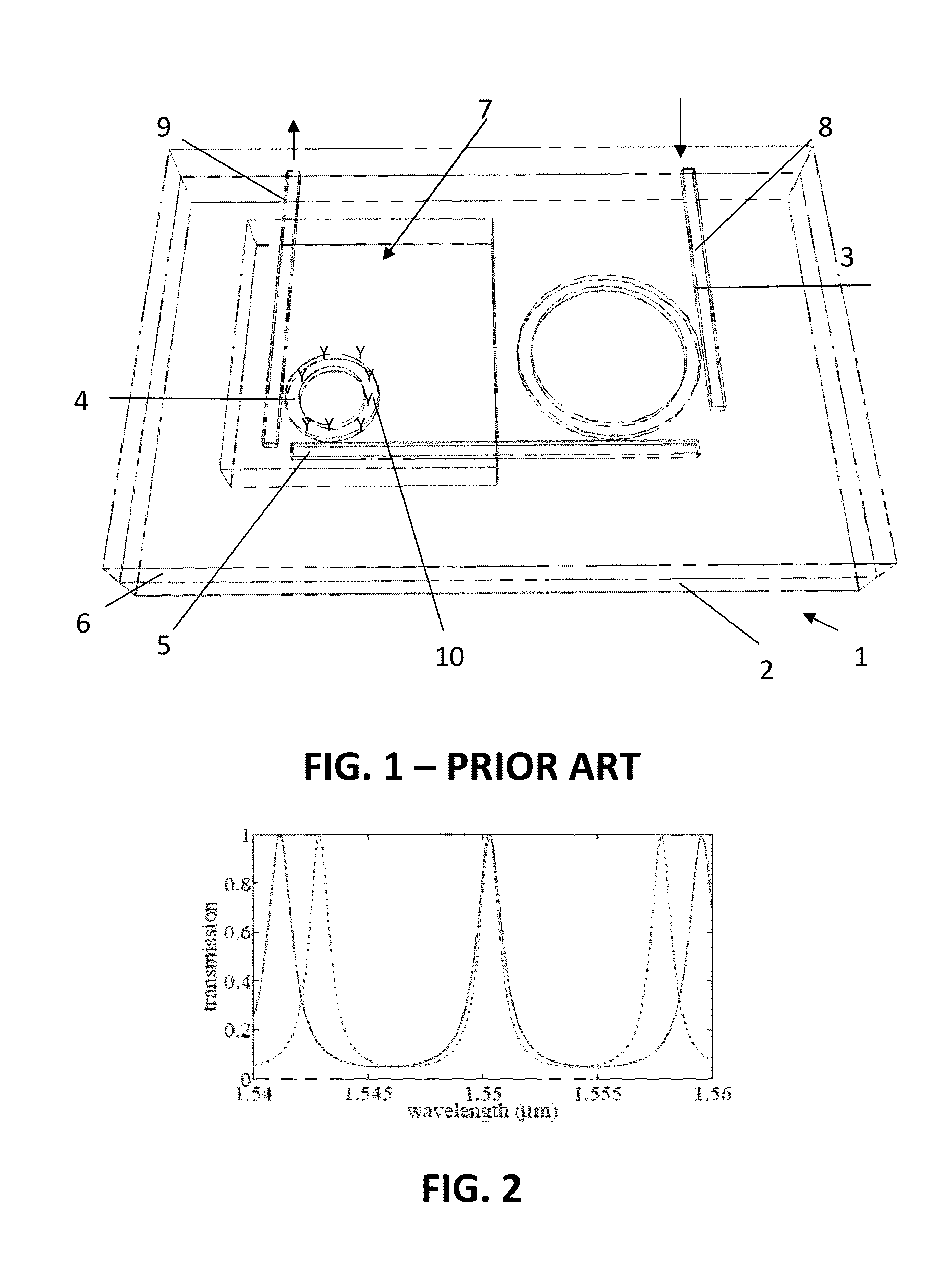
Slot waveguides with enhanced light-matter interaction may be applied to improve the sensitivity of ring resonator sensors with a factor two to four, but increased optical losses may prevented these sensors from achieving better detection limits than normal ring resonator sensors.
However, this known sensor operates as a digital, i.e. a discrete, sensor, which limits the smallest detectable shift and the detection limit of the sensor.
The smallest detectable shift of the transmission spectrum of this sensor is therefore equal to the free spectral range of the filter ring resonator, which forms a limitation to the detection limit of the sensor.

Method used


Image

  • Vernier photonic sensor data-analysis
  • Vernier photonic sensor data-analysis
  • Vernier photonic sensor data-analysis

Examples


Embodiment Construction

[0062]The present invention will be described with respect to particular embodiments and with reference to certain drawings but the invention is not limited thereto but only by the claims. The drawings described are only schematic and are non-limiting. In the drawings, the size of some of the elements may be exaggerated and not drawn on scale for illustrative purposes. The dimensions and the relative dimensions do not correspond to actual reductions to practice of the invention.

[0063]Furthermore, the terms first, second and the like in the description and in the claims, are used for distinguishing between similar elements and not necessarily for describing a sequence, either temporally, spatially, in ranking or in any other manner. It is to be understood that the terms so used are interchangeable under appropriate circumstances and that the embodiments of the invention described herein are capable of operation in other sequences than described or illustrated herein.

[0064]Moreover, t...


PUM

PropertyMeasurementUnit
detectable wavelength shiftaaaaaaaaaa
refractive indexaaaaaaaaaa

Abstract

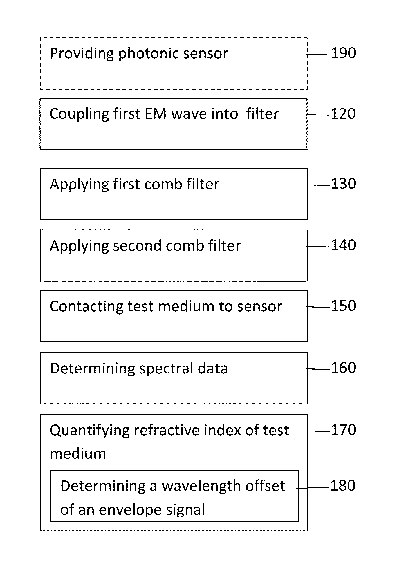
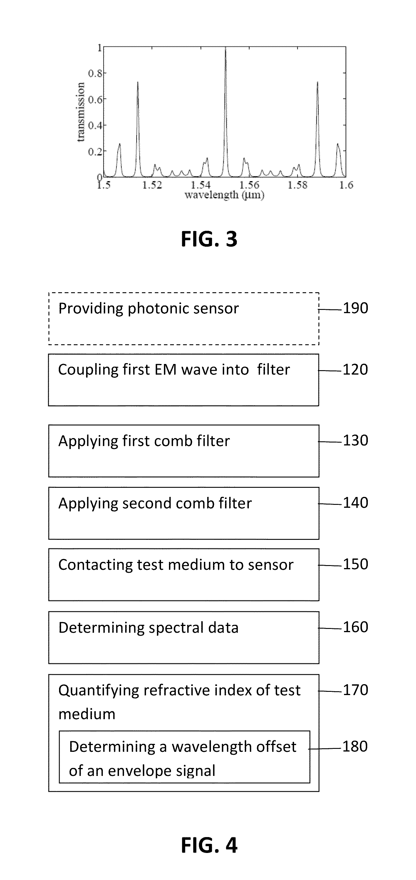
Quantifying a refractive index of a test medium by obtaining spectral data representative for an optical signal being modulated with an optical transfer characteristics of a photonic sensor, the modulation being obtained by combining modulation of a first electromagnetic wave component in an optical filter element with a first periodic transfer spectrum having a first free spectral range and modulation of a second electromagnetic wave component in an optical filter element with a second periodic transfer spectrum having a second free spectral range being different from the first free spectral range. A relative is change induced in the second periodic transfer spectrum by bringing the test medium in proximity with the optical filter element with the second periodic transfer spectrum. The refractive index of the test medium is quantified by determining a wavelength offset of an envelope signal in said spectral data.

Description

FIELD OF THE INVENTION[0001]The invention relates to the field of photonic sensors. More specifically it relates to the field of sensors for sensing effective refractive index changes in a photonic sensor and methods for analyzing data thereof.BACKGROUND OF THE INVENTION[0002]Label-free photonic biosensors can be used for performing sensitive and quantitative multiparameter measurements on biological systems and can therefore contribute to major advances in medical analyses, food quality control, drug development and environmental monitoring. Additionally they offer the prospect of being incorporated in laboratories-on-a-chip that are capable of doing measurements at the point-of-care at an affordable cost.[0003]A crucial component in most of these photonic biosensors is a transducer that can transform a refractive index change in its environment to a measurable change in an optical signal, e.g. an optical transmission signal. Silicon-on-insulator may be a material system with many ...

Claims


Application Information

Patent Timeline
Patent Type & Authority Applications(United States)
IPC IPC(8): G01N21/41
CPCG01N21/41G01N21/7746
Inventor BIENSTMAN, PETERCLAES, TOMBOGAERTS, WIM
Owner INTERUNIVERSITAIR MICRO ELECTRONICS CENT (IMEC VZW)
Why Eureka
Try Eureka