Temperature control device

a temperature control device and temperature control technology, applied in the direction of lighting and heating apparatus, machines using electric/magnetic effects, refrigerating machines, etc., can solve the problems of reducing the strength of the seal member, affecting the proper operation of the temperature control device, and damage to the seal member, so as to reduce the space required for providing the seal wall, increase the thickness of the seal wall, and enhance the strength of the seal wall

Inactive Publication Date: 2013-04-25
KELK LTD
View PDF12 Cites 29 Cited by
  • Summary
  • Abstract
  • Description
  • Claims
  • Application Information

AI Technical Summary

Benefits of technology

[0020]According to the first aspect of the invention, the thermoelectric module is spaced apart from and surrounded by the seal wall having a ceramic outer circumference and interposed between the protection member and the heat exchanger plate. Thus, the strength of the seal wall can be enhanced, the seal wall is not damaged by the high-temperature corrosive process gas, invasion of the highly corrosive process gas into the thermoelectric module can be prevented and failure of the temperature control device due to corrosion of the thermoelectric module can be avoided. Further, since it is not necessary to increase the thickness of the seal wall, the space required for providing the seal wall can be reduced, so that the thermoelectric module can be more densely provided and the temperature control of the object to be temperature-controlled can be more properly performed. Further, durability of the temperature control device against the heat of the process gas can be improved.
[0021]According to the second aspect of the invention, since the seal wall is made of aluminum oxide, aluminum nitride or alumited aluminum, the seal wall exhibits excellent resistance against a highly corrosive process gas.
[0022]According to the third and fourth aspects of the invention, since the protection member is made of a polyimide film or ceramic plate, the heat at least from the stage plate can be kept from being transferred to the seal wall. Thus, the seal wall can be thermally isolated from the stage plate and the seal wall can be kept from being heated to a high temperature due to the transferred heat. Further, since the thermoelectric module and the stage plate can be electrically insulated, an appropriate operation of the thermoelectric module can be ensured.
[0023]According to the fifth aspect of the invention, since the bush or the boss is provided, the process gas flowing from an outside of the thermoelectric module plate through the through hole can be kept from entering the thermoelectric module through the through hole, so that corrosion of the thermoelectric module can be avoided.

Problems solved by technology

However, in a typical temperature-control device, since the seal member is made of resin as disclosed in Literature 1 or is made of metal as disclosed in Literature 2, the strength of the seal member is reduced on account of the heat of the high-temperature process gas or a high corrosivity of the process gas, resulting in a damage on the seal member is damaged.
Thus, a highly corrosive process gas enters the thermoelectric module to corrode the thermoelectric module, thereby inhibiting the proper operation of the temperature-control device.
However, when the thickness of the seal member is increased, since the space occupied by the seal member in the thermoelectric module plate increases, the thermoelectric module cannot be densely arranged, so that the temperature of the object to be temperature-controlled cannot be appropriately controlled.
Further, since a metal plate is interposed between the top plate of the thermoelectric module plate and the seal member of the typical temperature-control device disclosed in Literature 2, a differential in thermal expansion generated due to the heat of the process gas between the top plate of the thermoelectric module plate and the seal member cannot be absorbed, so that the temperature-control device is damaged through the bonding portion between the top plate of the thermoelectric module plate and the seal member and the durability of the temperature-control device is deteriorated.

Method used


Image

  • Temperature control device
  • Temperature control device
  • Temperature control device

Examples


Embodiment Construction

[0032]A temperature control device according to an exemplary embodiment of the invention will be described below with reference to the attached drawings.

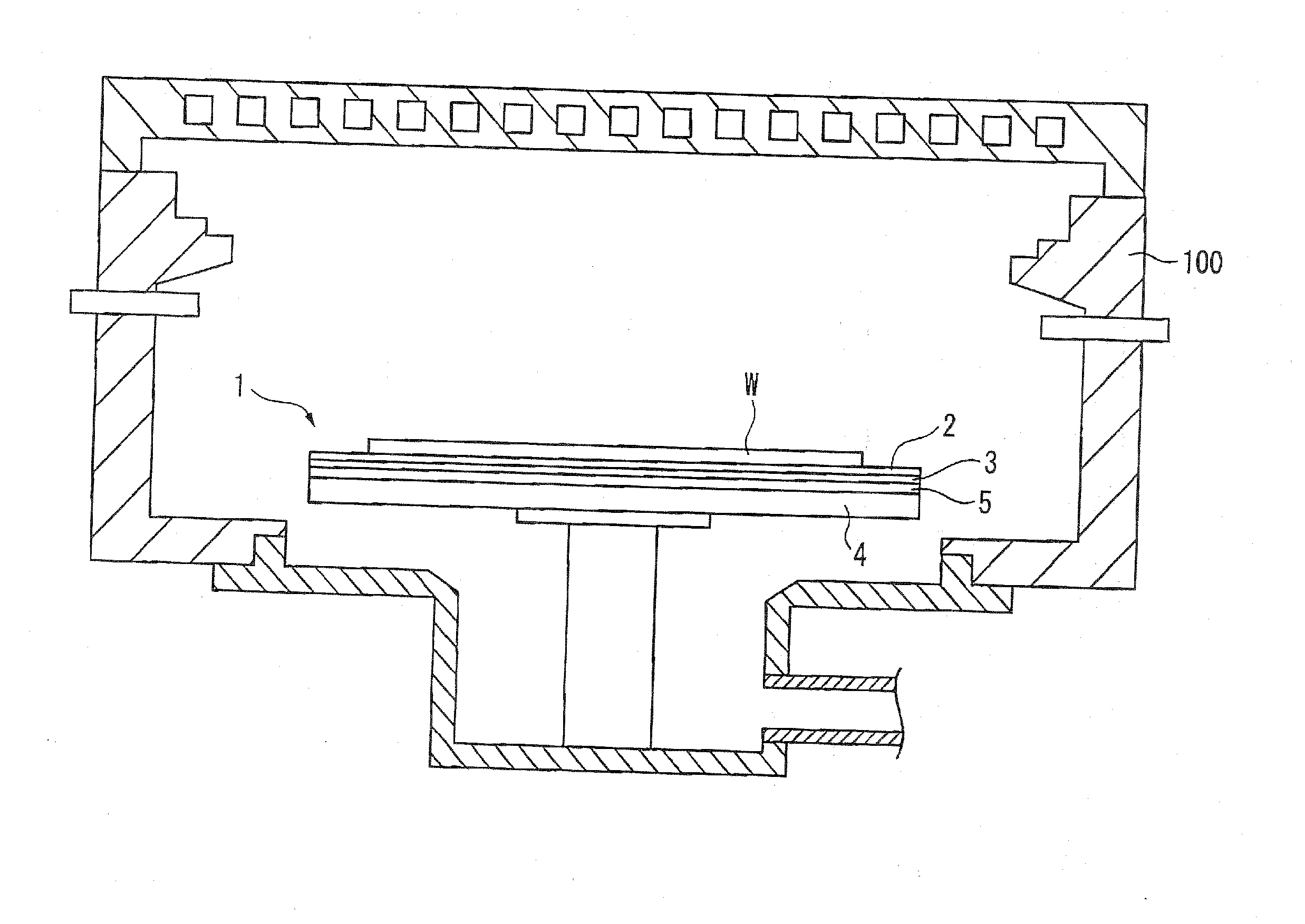
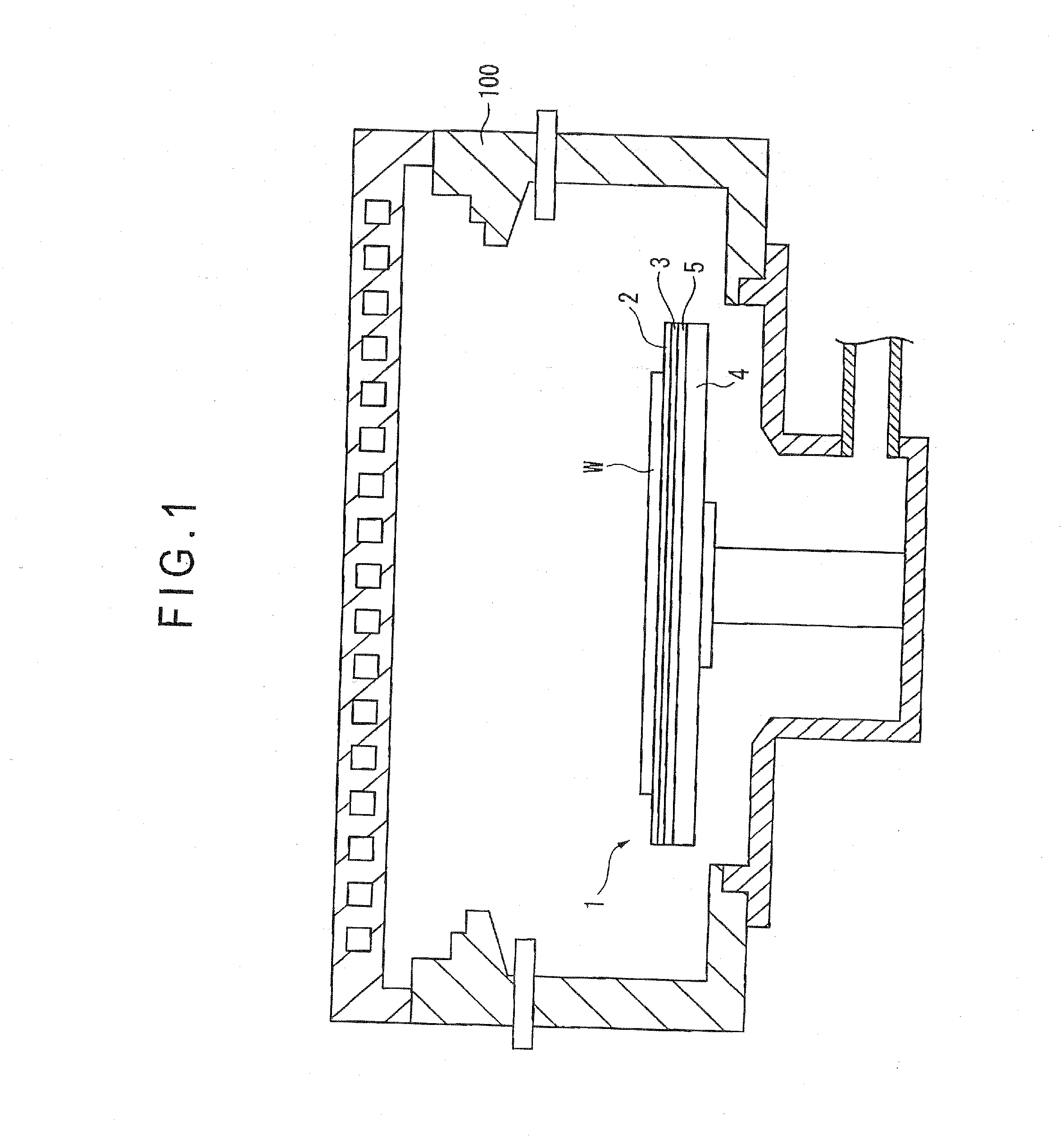
[0033]As shown in FIG. 1, a semiconductor wafer W (an object to be temperature-controlled) is a disc that is sucked and placed on a top plate 2 by an electrostatic chuck in a vacuum chamber 100 so that various semiconductor processing such as dry etching is performed on the semiconductor wafer with a process gas in a plasma atmosphere. When the semiconductor wafer is subjected to a dry etching, the inside of the vacuum chamber 100 is vacuumized and is kept at a predetermined low pressure. In this state, etching gas is introduced into the vacuum chamber 100. The introduced etching gas is turned into plasma for etching the semiconductor wafer W. When such various semiconductor processing is performed, the temperature of the semiconductor wafer W is controlled at a target temperature by the temperature control device 1 and a temperatur...


PUM


Abstract

A temperature control device includes: a top plate; a heat exchanger plate; a thermoelectric module including a temperature-control-side electrode disposed near the top plate, a heat-exchanger-side electrode disposed near the heat exchanger plate and a thermoelectric element of which one side is connected with the temperature-control-side electrode and the other side is connected with the heat-exchanger-side electrode; and a polyimide film provided on the thermoelectric module near the top plate. The thermoelectric module is spaced apart from and surrounded by a seal wall having a ceramic outer circumference and disposed between the polyimide film and the heat exchanger plate. An adhesion sheet or an adhesive is interposed between the seal wall and the polyimide film.

Description

[0001]The entire disclosure of Japanese Patent Applications No. 2011-229879 filed Oct. 19, 2011 and No. 2012-211942 filed Sep. 26, 2012 is expressly incorporated by reference herein.BACKGROUND OF THE INVENTION[0002]1. Field of the Invention[0003]The present invention relates to a temperature control device for controlling a temperature of an object to be temperature-controlled.[0004]2. Description of Related Art[0005]A semiconductor wafer (an object to be temperature-controlled) is placed on a stage plate of a susceptor provided in a vacuum chamber to be subjected to various semiconductor processing such as dry etching with a process gas in a plasma atmosphere. When the various semiconductor processing is performed, a temperature distribution on a surface of the semiconductor wafer has to be controlled as desired.[0006]A typically known temperature control device for performing the control includes a stage plate on which an object to be temperature-controlled is placed, a heat excha...

Claims


Application Information

Patent Timeline
Patent Type & Authority Applications(United States)
IPC IPC(8): F25B21/02
CPCF25B21/02F25B2321/021
Inventor TAKAHASHI, NORIOKIYOSAWA, WATARU
Owner KELK LTD
Why Eureka
Try Eureka