
Ocean wave energy system

a technology of energy systems and ocean waves, applied in the direction of electric generator control, machine/engine, vessel construction, etc., can solve the problems of corrosive ocean water, large variation of ocean waves in amplitude, wavelength and complexity, and requiring costly robust structures, so as to improve the efficiency of ocean wave energy systems

Active Publication Date: 2013-04-25
HAVKRAFT
View PDF6 Cites 55 Cited by
  • Summary
  • Abstract
  • Description
  • Claims
  • Application Information

AI Technical Summary

Benefits of technology

This patent seeks to improve the efficiency of ocean wave energy systems by using oscillating air columns to convert wave energy to useable energy. By adjusting the inclination angle of the columns, the system can more effectively match the natural periods of the columns to the received ocean waves. Additionally, the system includes a turbine arrangement for gyroscopic stabilization and submerged structures to improve wave coupling and dynamically adjust wave impedance matching. These improvements enable a greater portion of wave energy to be converted to output power from the system.

Problems solved by technology

Renewable energy systems adapted for generating energy from ocean waves have to contend with numerous technical challenges.
For example, ocean water is corrosive.
Moreover, ocean waves vary greatly in amplitude, wavelength and complexity with time.
Additionally, designers of ocean wave energy systems have to consider commercial viability of such systems in comparison to alternative systems such as wind turbine power generation systems, hydroelectric power systems, tidal power generation systems, fossil fuel burning power generation systems and nuclear power systems; many renewable energy systems suffer a problem of requiring costly robust structures, for example to withstand storm conditions, whilst generating relatively modest amounts of power when in operation in comparison to a corresponding size of a nuclear power station or fossil fuel power station.

Method used


Image

  • Ocean wave energy system
  • Ocean wave energy system
  • Ocean wave energy system

Examples


Embodiment Construction

[0088]In respect of describing embodiments of the present invention, contents of the aforementioned Norwegian patent no. NO 327593 (inventor: Geir Arne Solheim) are hereby incorporated by reference.

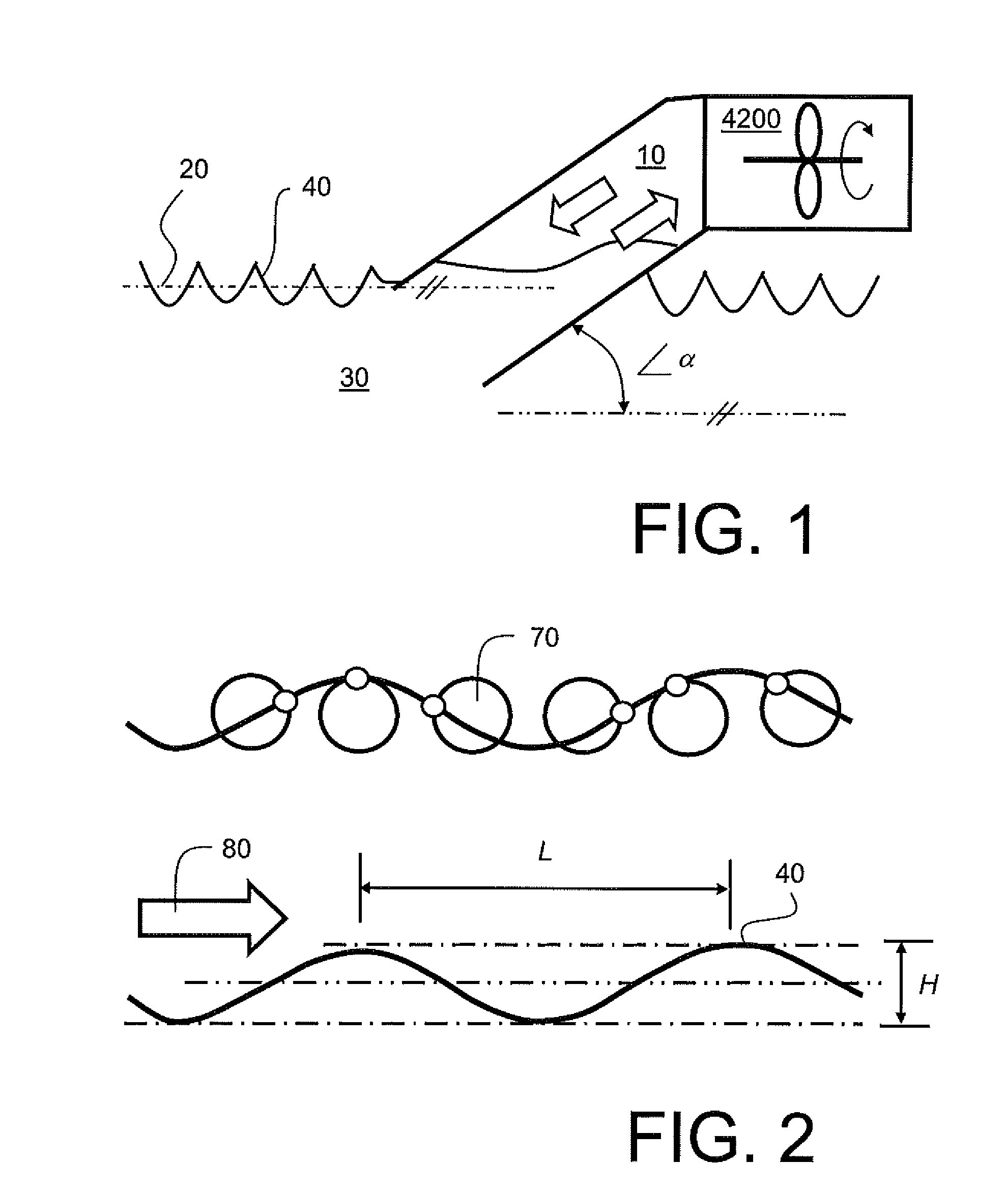
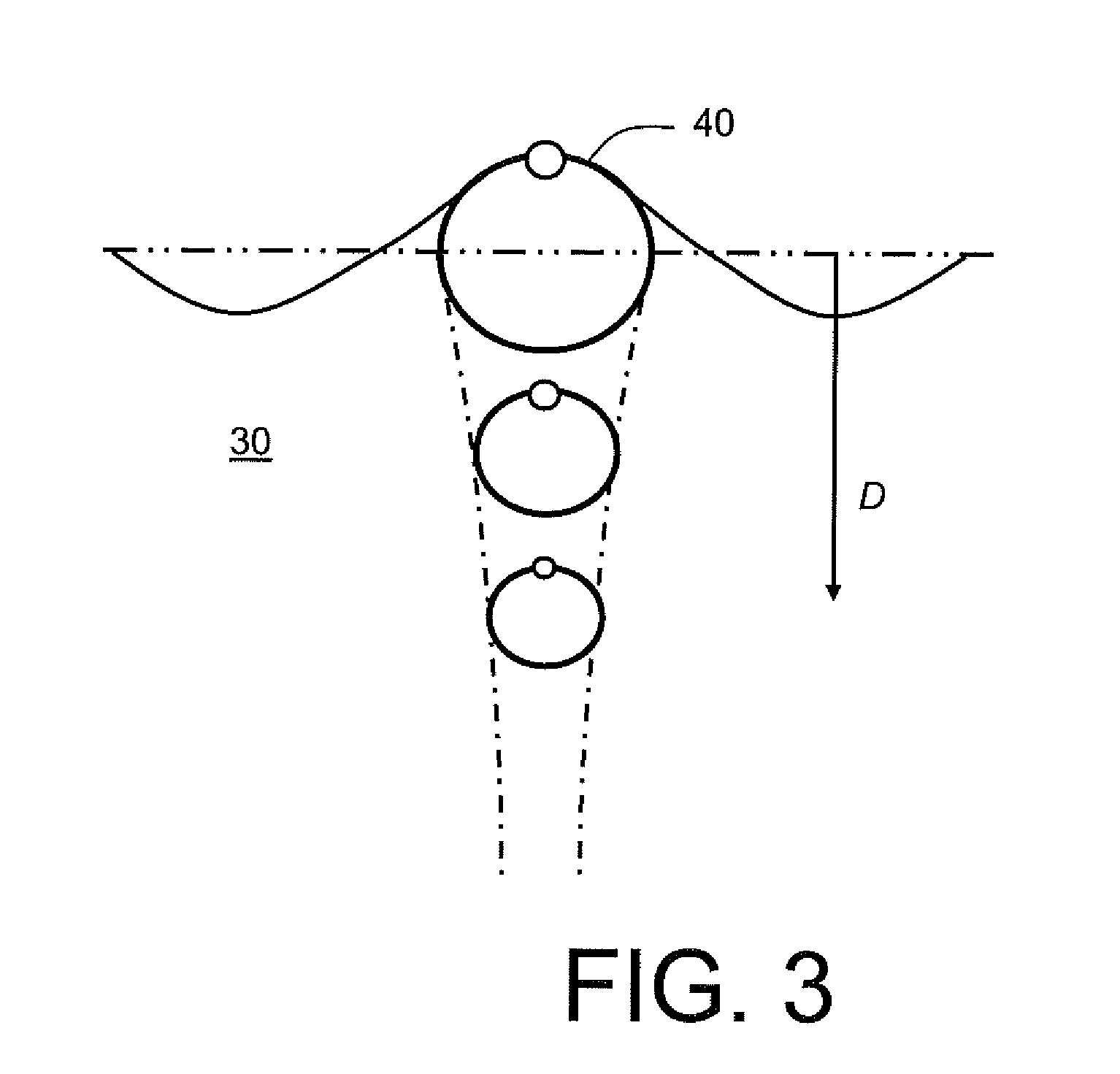
[0089]In order to further elucidate the present invention, some basic principles regarding ocean wave energy and ocean wave propagation characteristics will now be described. When an ocean wave 40 propagates, it corresponds to an energy flow; substantially circular cyclical water movement as denoted by 70 occurs as energy embodied in the ocean wave 40 propagates as illustrated in FIG. 2. A propagation direction of the wave 40 is denoted by an arrow 80. The wave 40 has a spatial wavelength of L and a trough-to-peak amplitude of H. When the wave 40 propagates with a velocity c, a frequency f of the wave 40 is defined by Equation 1 (Eq. 1):

f=cLEq.1

[0090]On account of oceans of Earth not having any preferred frequency for ocean wave propagation, namely no preferred resonant frequency characte...


PUM


Abstract

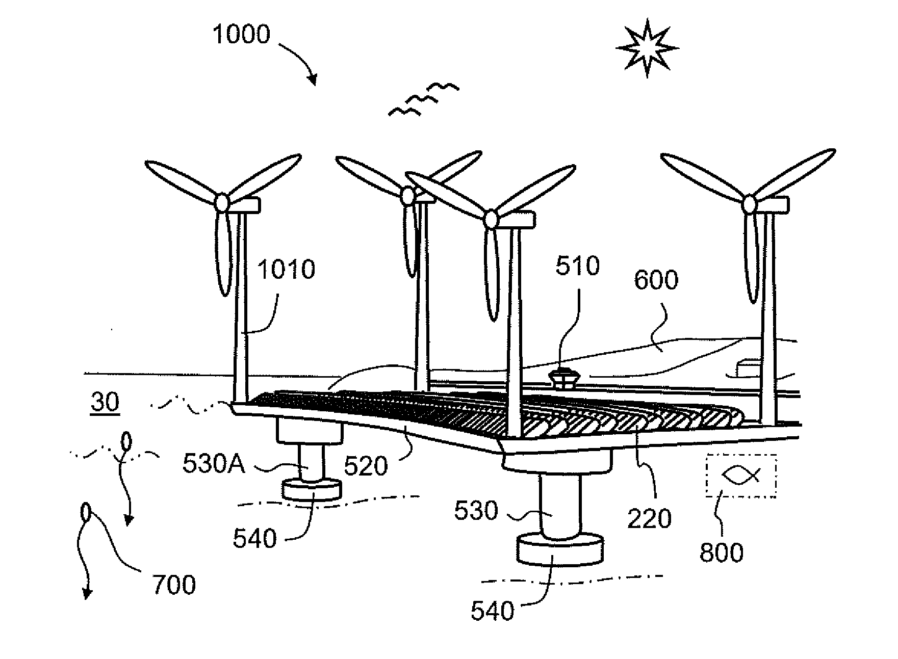
An ocean wave energy system for generating power from ocean waves includes a platform supporting an array of hollow columns whose respective lower ends are in fluidic communication with ocean waves and whose respective upper ends are in air communication with a turbine arrangement such that wave motion occurring at the lower ends is operable to cause air movement within the columns for propelling the turbine arrangement to generate power output. The system further includes one or more position-adjustable and / or angle-adjustable submerged structures near the lower ends of the columns for forming ocean waves propagating in operation towards the lower ends of the columns to couple the waves in a controllable manner into the hollow columns.

Description

FIELD OF THE INVENTION[0001]The present invention relates to ocean wave energy systems for generating energy from ocean wave motion, wherein the systems include one or more hollow tubes disposed at one or more non-vertical angles for receiving ocean waves at their one or more lower open ends, wherein the ocean waves are operable to compress in a cyclical manner fluid within the one or more hollow tubes for power generation purposes, and wherein the one or more hollow tubes are adapted so that their natural resonant frequency of wave motion therein is substantially equal in operation to a frequency of ocean waves received at the lower ends of the one or more hollow tubes for achieving enhanced energy conversion efficiency, for example by inclining and thereby changing hydrodynamic mass and stiffness of the one or more hollow tubes for modifying their natural resonant frequencies. Moreover, the present invention also relates to ocean wave energy systems for generating energy from ocea...

Claims


Application Information

Patent Timeline
IPC IPC(8): F03D9/00B63B21/50F03D7/02
CPCB63B21/50F03D7/0224F03D9/002Y02E10/38F03B13/142F03B13/24Y02E10/32F05B2210/404F05B2220/7068F05B2240/13F05B2250/314A01K61/007F05B2210/18A01K61/60F03D9/008F05B2240/97Y10T137/4238F03D13/25Y02E10/728Y02A40/81Y02E10/30Y02E10/72Y02P60/60F03D9/48F03D9/25
Inventor SOLHEIM, GEIR ARNE
Owner HAVKRAFT
Learn More