Methods for using a carbon dioxide capture system as an operating reserve

a carbon dioxide and operating reserve technology, applied in the control of electric generators, flue gas purification components, lighting and heating apparatus, etc., can solve the problems of power imbalance in the grid, substantial amount of energy, and reduce the efficiency of power plants

Inactive Publication Date: 2013-04-25
ALSTOM TECH LTD
View PDF4 Cites 8 Cited by
  • Summary
  • Abstract
  • Description
  • Claims
  • Application Information

AI Technical Summary

Benefits of technology

[0007]Exemplary embodiments of the present disclosure also include a method for providing an operating reserve to a power plant including: detecting a load imbalance; reducing a first percentage of steam from a boiler forwarded to a carbon dioxide capture system; increasing a second percentage of steam from the boiler forwarded to a steam cycle for electric generation; and maintaining a CO2 capture setpoint of the carbon dioxide capture system.

Problems solved by technology

These carbon dioxide capture systems require a substantial amount of energy to operate and therefore reduce the efficiency of the power plants.
Changes in both load and generation can result in a power imbalance in the grid.
These changes are not predictable or scheduled in advance.

Method used


Image

  • Methods for using a carbon dioxide capture system as an operating reserve
  • Methods for using a carbon dioxide capture system as an operating reserve
  • Methods for using a carbon dioxide capture system as an operating reserve

Examples


Embodiment Construction

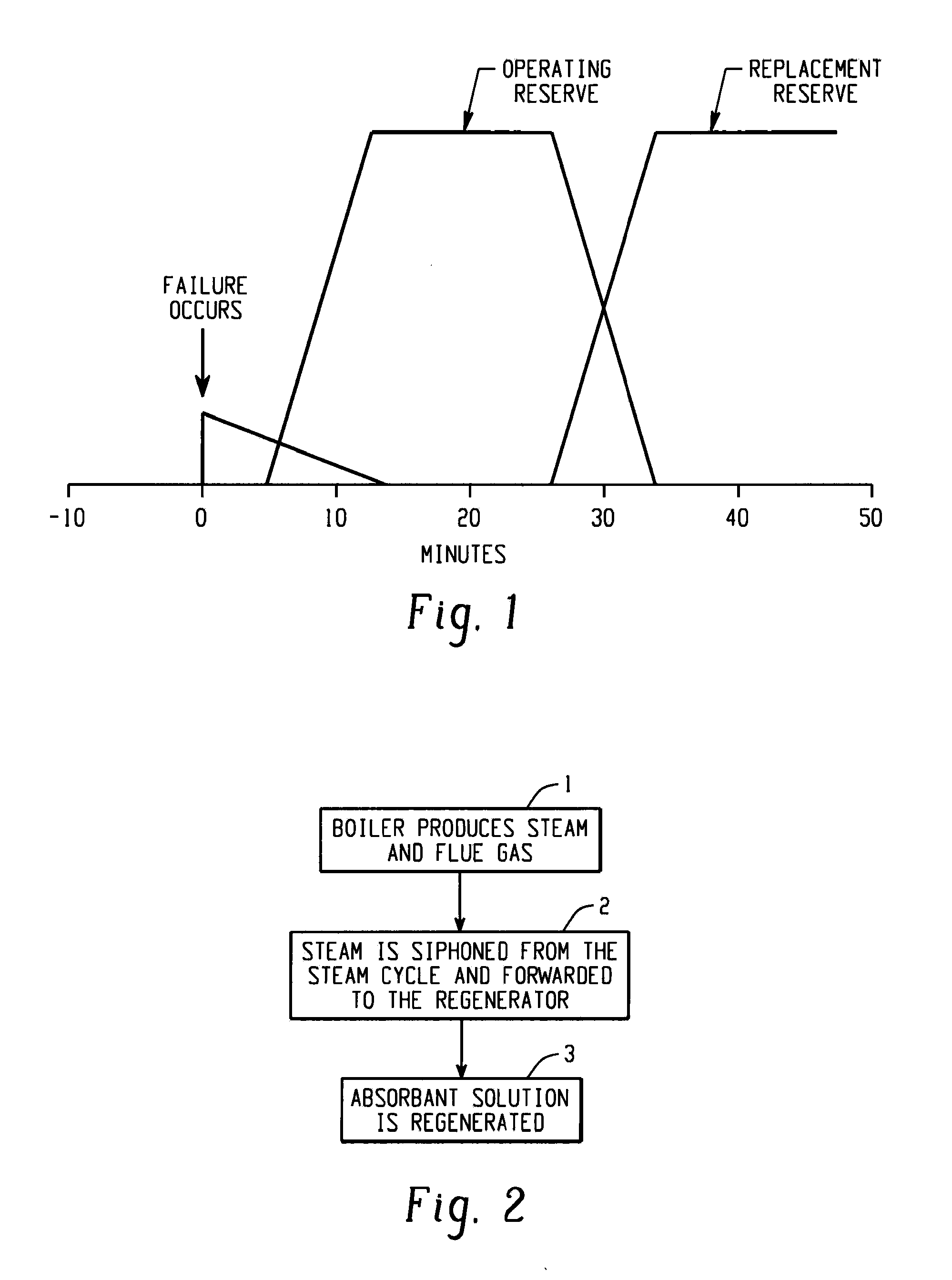
[0016]FIG. 1 is a graph illustrating the time periods over which the various types of reserve power are available to a system operator in response to a disruption in power supply or a spike in demand. In electricity network grids, the operating reserve is the generating capacity available to the system operator within a short interval of time to meet increases in demand that are caused by a generator going down or another disruption of power supply. Most power systems are designed so that, under normal conditions, the operating reserve is at least the capacity of the largest generator plus a fraction of the anticipated peak load.

[0017]The operating reserve is made up of a spinning reserve as well as a non-spinning or supplemental reserve. The spinning reserve is the extra generating capacity that is available by increasing the power output of generators that are already connected to the power system. For most generators, this increase in power output is achieved by increasing the to...


PUM


Abstract

A method of controlling a power system includes monitoring a load on an electrical grid, monitoring a power generation from one or more power producers connected to the electrical grid, wherein at least one of the one or more power producers is a power plant including a carbon dioxide capture system, and utilizing the carbon dioxide capture system of the one or more power producers as a operating reserve in response to an increase in the load on the electrical grid or a reduction in the power generation from one or more power producers connected to the electrical grid.

Description

BACKGROUND[0001]The present disclosure relates generally to systems and processes for controlling a electric power system. More specifically, the present disclosure relates to systems and processes configured to control a power system including one or more power plants integrated with a carbon dioxide capture system.[0002]Most of the energy used in the world today is derived from the combustion of carbon and hydrogen containing fuels such as coal, oil and natural gas, as well as other organic fuels. Such combustion generates flue gases containing high levels of carbon dioxide, a green house gas (GHG). Due to concerns about global warming, power plants that include carbon dioxide capture systems have been developed. These carbon dioxide capture systems require a substantial amount of energy to operate and therefore reduce the efficiency of the power plants.[0003]Electrical power consumption varies by the minute, hour and day. Changes in both load and generation can result in a power ...

Claims


Application Information

Patent Timeline
Patent Type & Authority Applications(United States)
IPC IPC(8): H02P9/04F22B3/00F01K13/00
CPCH02P9/04F01K13/02F01K17/02H02J3/46Y02C10/06H02J3/24F22B37/008Y02C20/40Y02E20/32Y04S20/222Y02B70/3225H02J3/241H02J3/466
Inventor HANDAGAMA, NARESHKUMAR B.KOTDAWALA, RASESH R.SHABDE, VIKRAM S.
Owner ALSTOM TECH LTD
Why Eureka
Try Eureka