
High performance foam and composite foam structures and processes for making same

a composite foam and high-performance technology, applied in the field of polymer foams and foamcontaining structures and methods of making, can solve the problems of high processing temperature, high energy absorption, and inability to meet the requirements of high stiffness, high strength and energy absorption, and achieve the effect of reducing pressure and temperature and great mechanical properties

Inactive Publication Date: 2013-05-09
BATTELLE MEMORIAL INST
View PDF4 Cites 19 Cited by
  • Summary
  • Abstract
  • Description
  • Claims
  • Application Information

AI Technical Summary

Benefits of technology

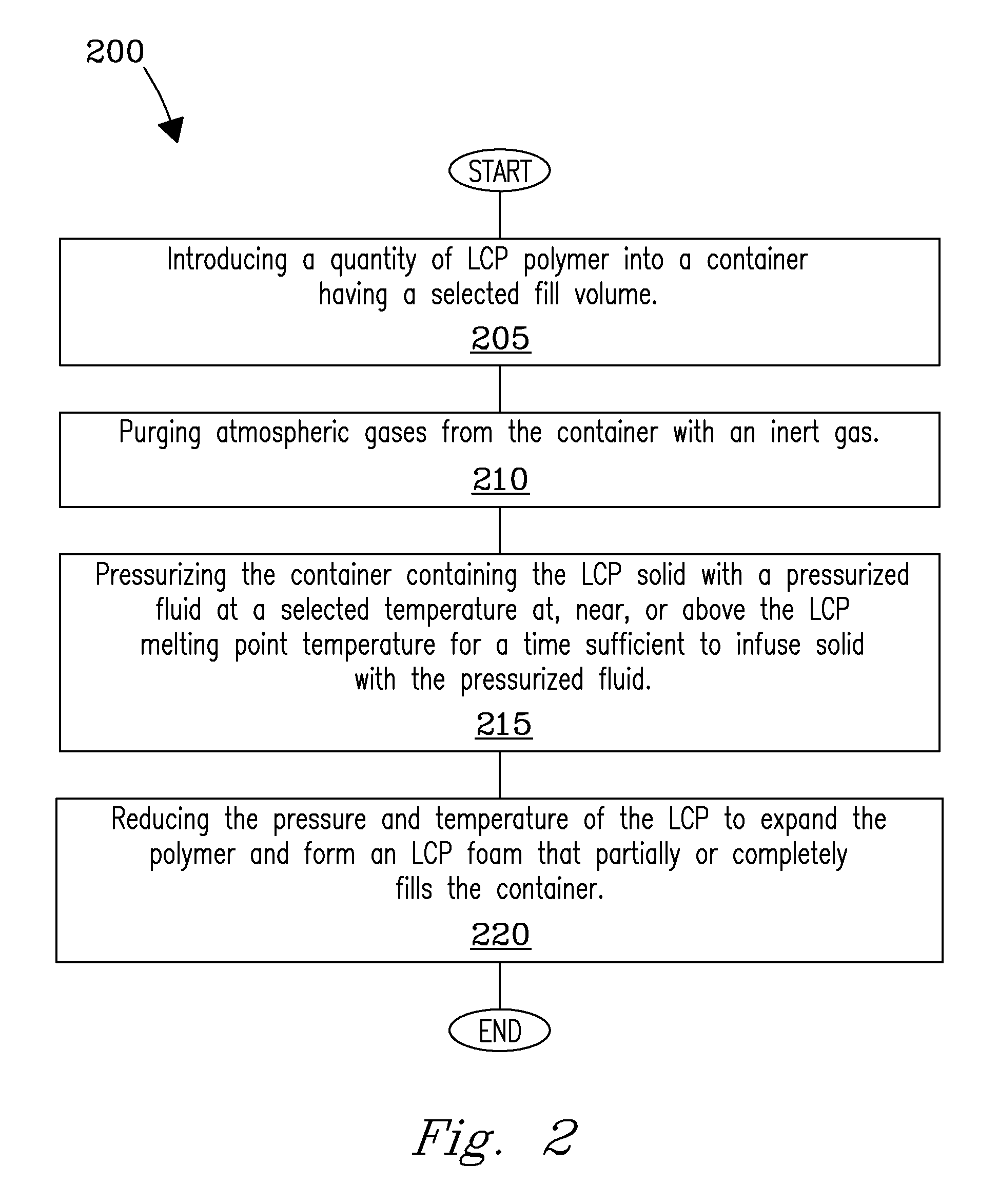
The patent describes a process for creating a thermal insulation material using a polymer called LCP. The process involves infusing the polymer with a fluidized gas at a high pressure, then reducing the pressure and temperature to cause the polymer to expand and solidify into a foam structure. The resulting foam has improved mechanical properties, including strength and energy absorption, compared to neat LCP polymer without a reinforcing phase. The foam can also be combined with other materials like fibers or particles to further enhance its properties. Overall, the process allows for the creation of a robust thermal insulation material with improved mechanical properties.

Problems solved by technology

Such foams are ell-suited for light-weight and low-energy absorption applications, but are not suitable for applications that require high stiffness, high strength, and high energy absorption properties.
While some metal foams (e.g., aluminum foams) are light-weight and possess a greater mechanical strength than do PU or PS foams, they are difficult to make due to their processing conditions.
The elevated temperatures required for processing and the difficulty associated with integrating planar structures into complex and contoured parts e.g., hollow tubes, remains a problem.
Other processing challenges exist with metal foams including, e.g., release of hazardous gases.
The mixture is then heated near the melting temperature of aluminum to decompose the TiH2, which forms the aluminum foam but also releases H2 gas—a chemical hazard.
Another problem with metal foams is that the compressive strength and modulus scale as a function of the foam density.
This means that low density metal foams typically exhibit a low compressive strength and modulus, and vice-versa.

Method used


Image

  • High performance foam and composite foam structures and processes for making same
  • High performance foam and composite foam structures and processes for making same
  • High performance foam and composite foam structures and processes for making same

Examples


example

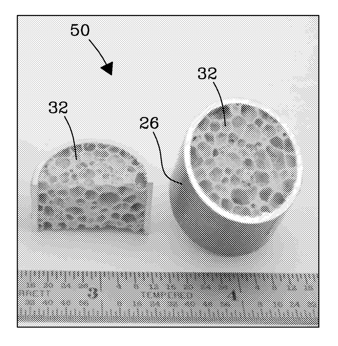
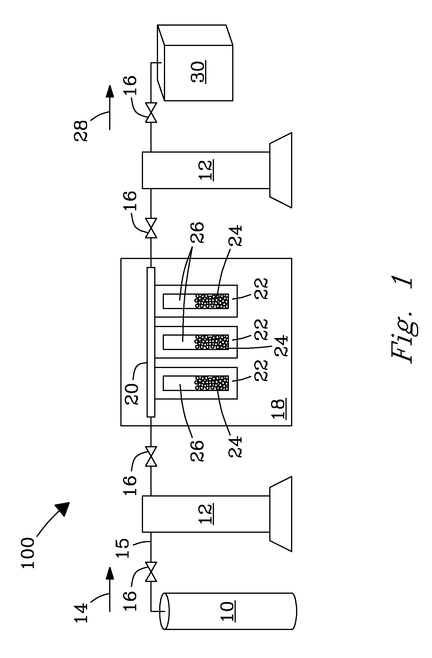
[0102]˜400 mg of pellets of VECTRA-B130 LCP 24 were placed inside a glass vial container 26 (dimensions ˜35 mm in length and outer diameter of ˜8 mm). Pellets filled vial container 26 up to approximately half the available height. Glass container 26 was placed inside a high pressure containment vessel 22 that was connected to a stainless steel manifold 20. Foaming system 100 was assembled as follows. Glass vials 26 containing pellets of LCP 24 were placed within high pressure containment vessel 22 and installed within the high pressure foaming manifold 20 located inside oven 18. System 100 was purged ˜10 minutes with flowing argon gas, and then pressurized to about 4200 psi with argon, and stabilized. Oven 18 was then energized to initiate heating in oven 18. Temperature was raised incrementally to a temperature of 320° C. (˜15 minutes), and system 100 was held isothermally at 320° C. and 4200 psi argon pressure for 60 minutes to infuse the LCP with the fluidized gas. Following the ...


PUM

PropertyMeasurementUnit
pressureaaaaaaaaaa
specific energy absorptionaaaaaaaaaa
temperaturesaaaaaaaaaa

Abstract

Methods are disclosed for making liquid crystalline polymer (LCP) foams and foam structures of various shapes and forms. LCP foams of the invention have a high compression strength suitable for high performance energy-absorption and energy-impact applications and devices.

Description

STATEMENT REGARDING RIGHTS TO INVENTION MADE UNDER FEDERALLY-SPONSORED RESEARCH AND DEVELOPMENT[0001]This invention was made with Government support under Contract DE-AC05-76RLO-1830 awarded by the U.S. Department of Energy. The Government has certain rights in the invention.FIELD OF THE INVENTION[0002]The present invention relates generally to polymer foams and foam-containing structures and methods of making. More particularly, the invention relates to high performance liquid crystalline polymer (LCP) foams and composite foam structures and processes for making same.BACKGROUND OF THE INVENTION[0003]Current needs exist for light-weight, high-strength materials that can be easily processed and mass produced in an industrial setting for use in structural components (e.g., within motor vehicles). Polyurethane (PU) or polystyrene (PS) foams are common foams that are relatively soft and have a low compressive strength. Such foams are ell-suited for light-weight and low-energy absorption...

Claims


Application Information

Patent Timeline
Patent Type & Authority Applications(United States)
IPC IPC(8): B29C44/18B05D7/24C08G63/685C08J9/00C08J9/08C08J9/14C08J9/10B29C44/34C08G63/06
CPCB29C44/3453C08J2367/00C08J9/00C08J9/08C08J9/10C08J9/14C08G63/06C08G63/685C08J9/122C08J2201/032C08J2203/06C08J2203/08C08J9/0066C08J2300/12B29C44/348B29C70/545
Inventor ROHATGI, AASHISHADDLEMAN, RAYMOND S.BUSCHE, BRADLEY J.
Owner BATTELLE MEMORIAL INST
Learn More