Process for producing acetic acid

a technology of acetic acid and acetic acid, which is applied in the preparation of carboxylic compounds, carbon monoxide reaction carboxylic preparations, organic chemistry, etc., can solve the problems of insufficient heat removal method utilizing latent heat of evaporation to remove reaction heat, small amount of heat removed, and high cost of equipment. , to achieve the effect of high purity, high yield and high purity

Active Publication Date: 2013-05-09
DAICEL CHEM IND LTD
View PDF3 Cites 49 Cited by
  • Summary
  • Abstract
  • Description
  • Claims
  • Application Information

AI Technical Summary

Benefits of technology

[0016]According to the present invention, in a process for producing acetic acid with a high purity by allowing at least one member selected from the group consisting of methanol, dimethyl ether, and methyl acetate to continuously react with carbon monoxide, since part of the vaporized stream withdrawn from a flasher is introduced into the heat exchanger and condensed to recycle the condensed fraction to the reactor, part of the quantity of heat transferred from the reaction solution to the flash vapor can be removed before heat removal utilizing a latent heat of evaporation in the distillation column even for a large-sized plant, it is unnecessary to install a cooling unit in the reactor, and carbon monoxide dissolved in the reaction solution can be utilized effectively. Thus, even for a large-sized plant, the loss of carbon monoxide can be inhibited in a resource-saving and energy-saving equipment having a miniaturized apparatus (e.g., a distillation column), and acetic acid with a high purity can be produced with a high yield.

Problems solved by technology

Thus, only the heat removal method utilizing the latent heat of evaporation is insufficient for removing the reaction heat.
However, according to the method for providing the catalyst recycle line with the cooling unit, since sensible heat is used for the heat removal, it is necessary to install an expensive equipment using a high-grade material with a high corrosion resistance, and the amount of removed heat is small.
Moreover, according to the method for providing the reactor with the cooling unit, since a reaction solution as well as the reactor is exposed to a high temperature and a high pressure, carbon monoxide dissolved in the reaction solution is consumed in pipelines.
Thus, it is difficult to maintain an active state of a rhodium-carbonyl complex as an active catalyst species (for example, [RhI2(CO)2]−, [RhI2(CO)4]−).
The main catalyst Rh does not contribute to the reaction due to sedimentation thereof, e.g., in the state of RhI3, or the sediment blockades the pipeline or the like and causes incomplete actions of a valve, a pump, or the like, and it is difficult to operate the system stably.
However, the equipment for the use under a high temperature and a high pressure is expensive, and the reaction solution is easy to leak.
Thus, it is difficult to operate the system stably.
However, in the method for removing heat by the condenser installed to the top of the distillation column, the condenser is subjected to a large load, and the cost of equipment or the energy cost is so large that it can no more be disregarded.
However, for a large-sized plant, only cooling of the liquid (sensible heat) is insufficient to remove the heat.

Method used


Image

  • Process for producing acetic acid

Examples


example 1

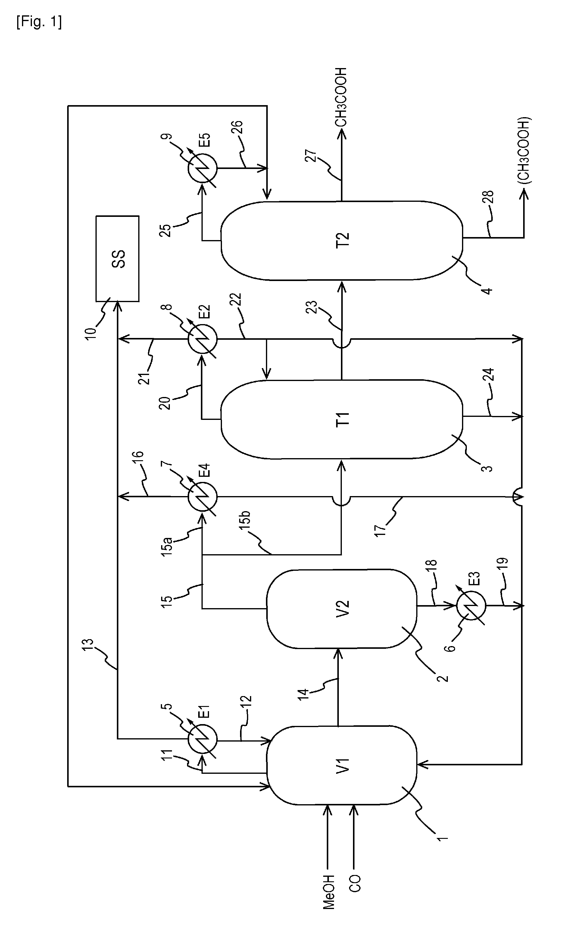
[0096]The plant shown in the diagram of FIG. 1 was continuously operated in the same manner as in Comparative Example 1. Specifically, the reaction heat was removed by using the condenser E1, the condenser E2, the heat exchanger E3, and the heat exchanger E4. The yield and purity of the resulting acetic acid in Example 1 ware almost the same as those in Comparative Example 1.

[0097]The balance of the heat quantity in the plant of Comparative Example 1 and that in the plant of Example 1 were compared. The results are shown in Table 1.

TABLE 1Balance of Heat Quantity [unit: kcal / hour]TotalE1E2E3E4quantityCom. Ex. 11.9 × 1053.4 × 107——3.4 × 10⁷Ex. 11.9 × 1052.0 × 1077.1 × 1066.3 × 1063.4 × 107

[0098]Moreover, assuming that the feed amount (t / hour) of the condenser E1 in Comparative Example 1 was 1, the feed amount of the first distillation column T1, that of the heat exchanger E3, and that of the heat exchanger E4 were expressed as relative values. The results are shown in Table 2.

TABLE 2...

example 2

[0102]The plant shown in the diagram of FIG. 1 was continuously operated in the same manner as in Comparative Example 2. Specifically, the reaction heat was removed by using the condenser E1, the condenser E2, the heat exchanger E3, and the heat exchanger E4. Incidentally, as described later, Example 2 is different in feed amount from Example 1. The yield and purity of the resulting acetic acid in Example 2 ware almost the same as those in Comparative Example 2.

[0103]The balance of the heat quantity in the plant of Comparative Example 2 and that in the plant of Example 2 were compared. The results are shown in Table 4.

TABLE 4Balance of Heat Quantity [unit: kcal / hour]TotalE1E2E3E4quantityCom. Ex. 21.9 × 1052.2 × 1071.2 × 107—3.4 × 10⁷Ex. 21.9 × 1052.0 × 1071.2 × 1072.5 × 1063.4 × 107

[0104]Moreover, assuming that the feed amount (t / hour) of the condenser E1 in Comparative Example 1 was 1, the feed amount of the first distillation column T1, that of the heat exchanger E3, that of the h...

example 3

[0108]The plant shown in the diagram of FIG. 1 was continuously operated in the same manner as in Comparative Example 3. Specifically, the reaction heat was removed by using the condenser E1, the condenser E2, the heat exchanger E3, and the heat exchanger E4. The yield and purity of the resulting acetic acid in Example 3 ware almost the same as those in Comparative Example 3.

[0109]The balance of the heat quantity in the plant of Comparative Example 3 and that in the plant of Example 3 were compared. The results are shown in Table 7.

TABLE 7Table 7 Balance of Heat Quantity [unit: kcal / hour]TotalE1E2E3E4E6quantityCom. 6.2 × 1051.1 × 107 0.6 × 10⁷ —1.6 ×3.4 × 107 Ex. 3107 Ex. 36.2 × 1051.1 × 1071.0 × 1071.2 × 107 —3.4 × 10⁷

[0110]Moreover, assuming that the feed amount (t / hour) of the condenser E1 in Comparative Example 1 was 1, the feed amount of the first distillation column T1, that of the heat exchanger E3, that of the heat exchanger E4, that of the second distillation column T2, and...


PUM

PropertyMeasurementUnit
partial pressureaaaaaaaaaa

Abstract

A production process of acetic acid comprises a reaction step for continuously allowing at least one member selected from the group consisting of methanol, dimethyl ether, and methyl acetate to react with carbon monoxide in a catalyst system comprising a rhodium catalyst, an iodide salt, and methyl iodide in the presence of acetic acid and water in a plant compromising a reactor 1; a flasher 2; and a distillation column 3; wherein part of the vaporized stream is introduced into a heat exchanger 7. The process achieves a production of acetic acid with a high purity in a resource-saving and energy-saving equipment by efficiently removing a reaction heat even in a large-sized plant.

Description

TECHNICAL FIELD[0001]The present invention relates to a process for producing acetic acid with a high purity in a resource-saving and energy-saving equipment in a large-sized plant.BACKGROUND ART[0002]In a plant for producing acetic acid using a methanol method, carbon monoxide is allowed to react with methanol in a carbonylation reactor, the reaction solution is vaporized by an evaporator (flasher), and the resulting vaporized product is further distilled by a distillation column for separation to produce acetic acid. Since such steps generates reaction heat due to the carbonylation reaction, it is necessary to remove the reaction heat. As a system for removing the reaction heat in this plant, a method of removing the reaction heat by utilizing a latent heat of evaporation of acetic acid generated in an evaporator and a latent heat of evaporation of constituents (e.g., methyl iodide, methyl acetate, water, and other by-products) of the reaction solution accompanying acetic acid eva...

Claims


Application Information

Patent Timeline
Patent Type & Authority Applications(United States)
IPC IPC(8): C07C51/12
CPCC07C51/12C07C51/43C07C51/44C07C53/08Y02P20/10
Inventor MIURA, HIROYUKISHIMIZU, MASAHIKOUENO, TAKASHIYAMAGUCHI, KAZUOGOTO, KENSUKE
Owner DAICEL CHEM IND LTD
Why Eureka
Try Eureka