Liquid-air transpired solar collectors

Inactive Publication Date: 2013-05-16
MASDAR INST OF SCI & TECH
View PDF9 Cites 8 Cited by
  • Summary
  • Abstract
  • Description
  • Claims
  • Application Information

AI Technical Summary

Benefits of technology

[0004]According to some aspects of the invention, solar energy collectors are provided. In some embodiments, the solar energy collectors have a relatively low cost of construction compared with conventional solar collectors. In some embodiments, collectors are provided that operate at relatively high efficiencies under light wind conditions. In some embodiments, collectors are provided in an unglazed configuration that facilitates convection driven by wind which controls the temperature

Problems solved by technology

However the capital cost of installing water heating collectors remains an obstacle to in its widespread use.
However for lower suction veloc

Method used


Image

  • Liquid-air transpired solar collectors
  • Liquid-air transpired solar collectors
  • Liquid-air transpired solar collectors

Examples


example 1

LATSC Numerical Model

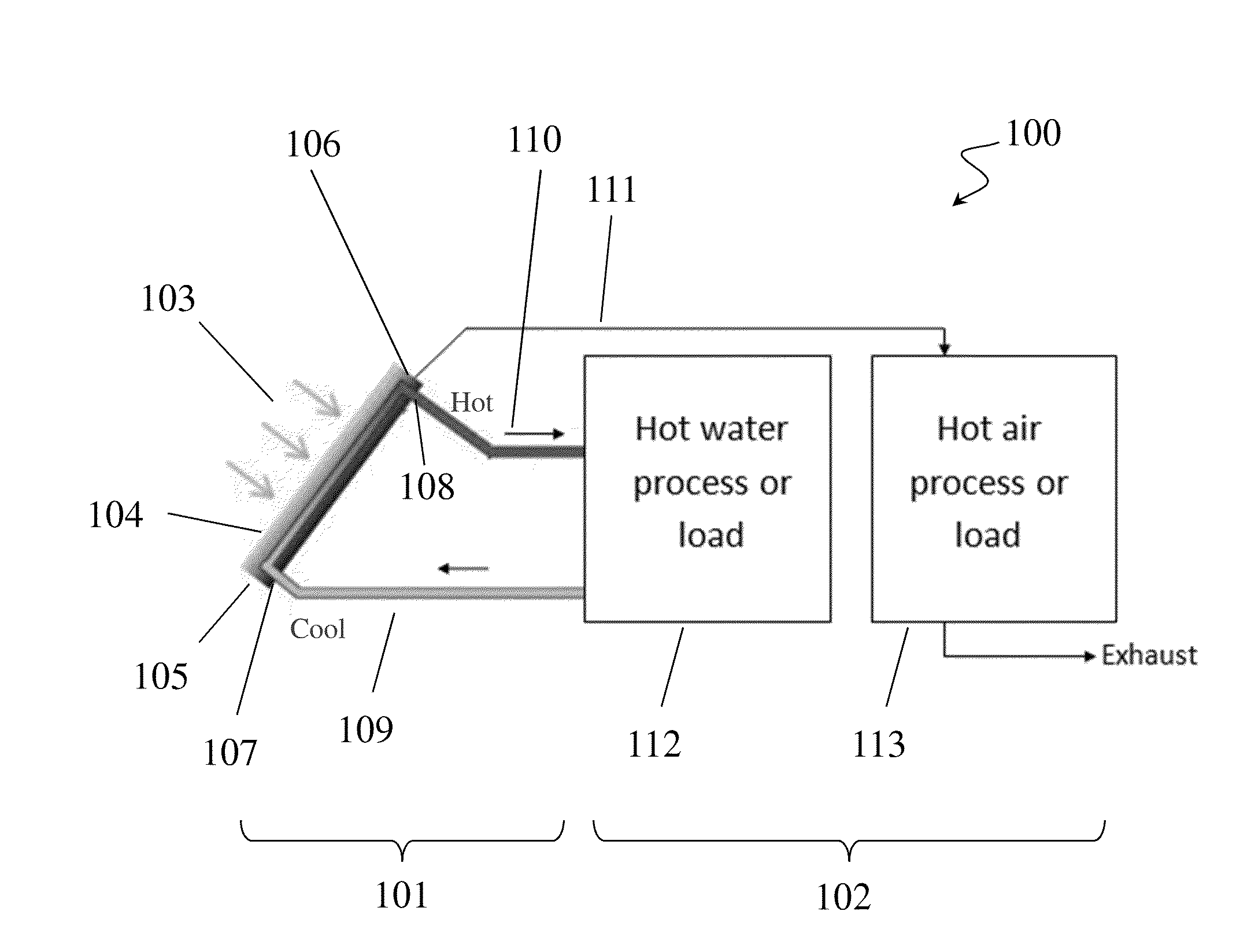
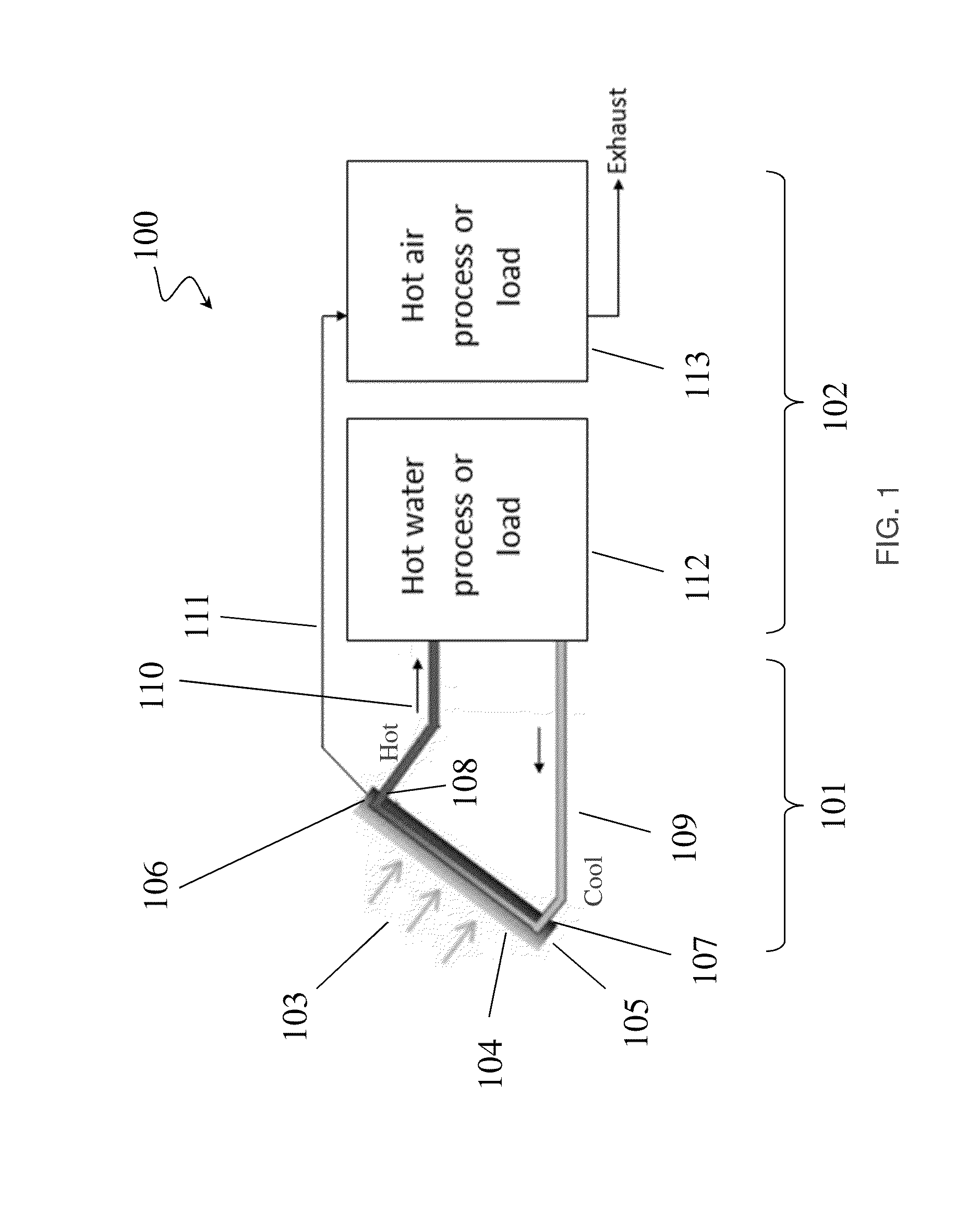
[0090]This example relates to a hybrid solar collector referred to as a Liquid-Air Transpired Solar Collector (LATSC). The LATSC is useful for processes that utilize both hot air and hot water. A schematic of a LATSC supplying heat to two processes is depicted FIG. 1. In developing a numerical model of the LATSC, heat transfer mechanisms from the absorber plate and from the back of the collector were considered.

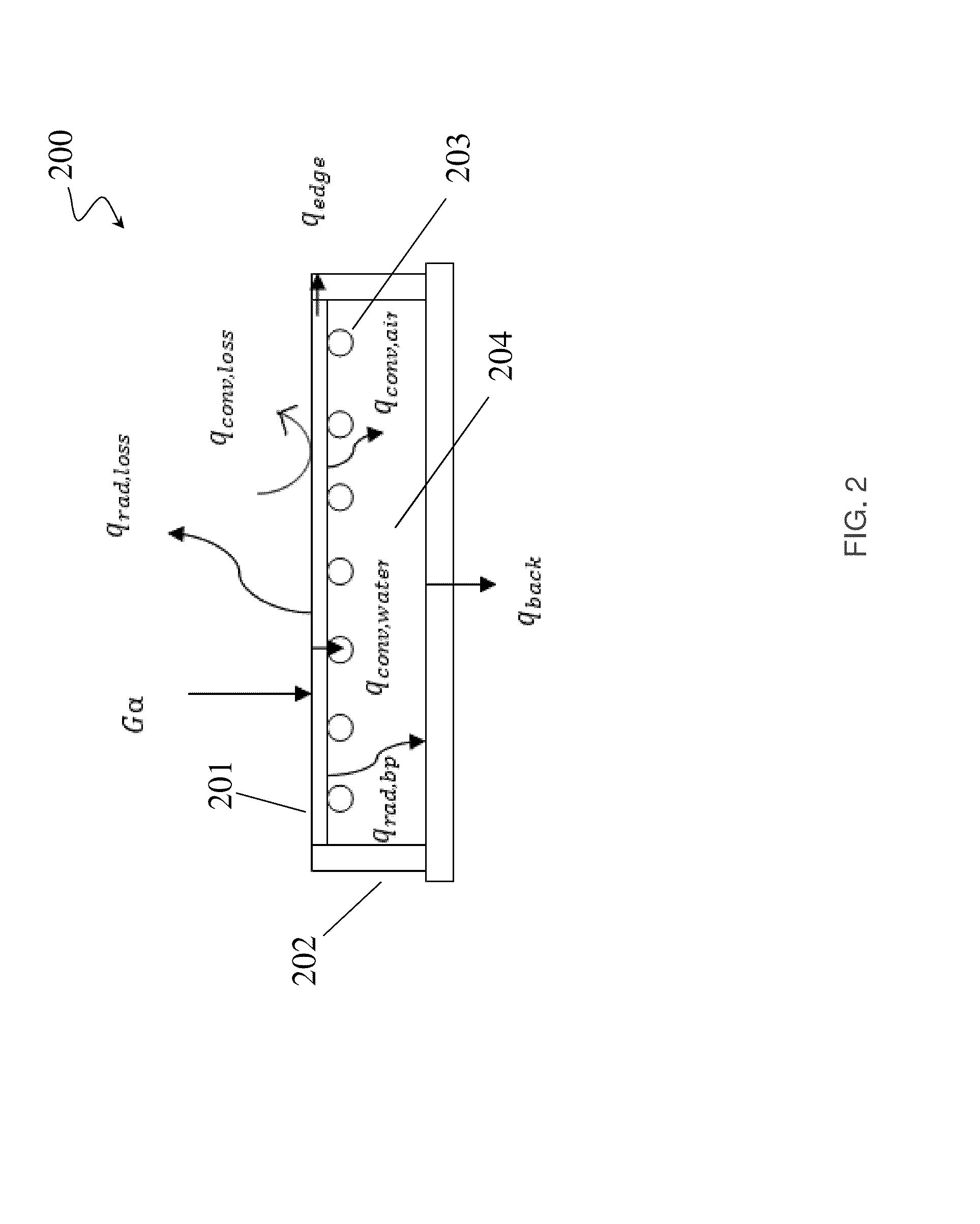
[0091]A schematic diagram in FIG. 2 shows the different modes of heat transfer in a cross-section of a solar energy collector 200. The solar energy collector 200 includes a housing 202 forming a cavity 204 for containing a fluid, and solar absorber 201 connected with the housing 202. The solar energy collector 200 also includes a plurality of conduits 203 in the cavity. Losses were categorized as convective and radiative front of plate losses (qconv,loss, qrad, loss), convective and radiative back of plate losses (qconv,air,qrad,bp) and back of collector ...

example 2

Sensitivity Analysis of the LATSC Model

Sensitivity Analysis

[0144]With the collector model described in Example 1, the performance sensitivity of the collector to varying the ambient temperature (Tamb), inlet water temperature (Twi), collector emissivity (ε), solar radiation (G), wind speed (Vw) and total thermal capacitance of air and water ({dot over (m)}cp)total was evaluated. Moreover for each analysis, the ratio of thermal capacitance of air to total thermal capacitance (R{dot over (m)}cp) was varied to observe its effect on the efficiency of the collector along with the other varying parameters. The efficiency of the collector was given by:

ηc=m.aCpa(Tao-Tai)+m.wCpw(Two-Twi)G*A(53)

[0145]Two batches of sensitivity analysis were performed. The first batch evaluated the performance of the collector to changes in ({dot over (m)}cp)total and (R{dot over (m)}cp) with other physical and weather parameters held constant while the second batch was aimed at producing performance curves fo...

example 3

Experimental Assessment of LATSC

[0160]To further evaluate the model disclosed in Examples 1 and 2, an experiment was conducted to test a LATSC. A LATSC was constructed which comprises a 2 m2 flat plate, tube-fin type, collector, as depicted in FIG. 32.

[0161]The thermal testing of the collector involved accurate measurement of both the total solar energy incident and the total thermal energy gain of the collector. The solar energy incident was measured by the use of pyranometers and accurate measurement of the collector absorber area. Assessment of the thermal energy gain involved the measurement of the inlet and outlet temperatures of air and water as well as their respective flow rates. The total thermal energy gain of the collector was given by:

Qu,tot=[{dot over (m)}Cp(Tout−Tin)]a+[{dot over (m)}Cp(Tout−Tin)]w  (55)

[0162]The specific heat capacity of water and air were calculated in EES using established property data as a function of temperature and pressure.

[0163]The efficiency ...


PUM


Abstract

The invention, in some embodiments, relates to solar energy collectors, and methods of use thereof. In some embodiments, the invention relates to liquid-air transpired solar energy collectors, and methods of use thereof. In some embodiments, the invention relates to thermal energy transfer systems that comprise solar energy collectors, and methods of use thereof. In some embodiments of the invention, methods of constructing solar energy collectors are provided.

Description

FIELD OF THE INVENTION[0001]The invention generally relates to solar energy collectors and methods of use thereof.BACKGROUND OF INVENTION[0002]Solar water heating collectors have been used for domestic water heating for decades as they provide considerable savings in energy bills. Conventional flat-plate water heating collectors can provide high solar to thermal energy conversion efficiency and can fulfill many of the water heating demands of a building when storage of about one day's water use is provided. However the capital cost of installing water heating collectors remains an obstacle to in its widespread use.[0003]Transpired collectors actively pull air through small perforations in the absorber plate which leads to the heating of the air. The air movement suppresses convection losses as the heat conducted to the thermal boundary layer is continuously pulled back toward the plate. A transpired solar collector can perform efficiently at high suction velocities. However for lowe...

Claims


Application Information

Patent Timeline
IPC IPC(8): F24J2/04F24J2/24F24J2/46F24J2/30F24S10/30F24S10/50F24S10/70
CPCF24J2/0477Y02E10/44Y02B10/20F24S80/457F24S40/90F24S10/20F24S10/501F24S10/80F24S60/30F24S70/65F24S10/30F24S10/40
Inventor ARMSTRONG, PETER ROSSQADIR, ABDULCHIESA, MATTEO
Owner MASDAR INST OF SCI & TECH
Why Eureka
Try Eureka