Aerosol generator assembly

a technology of generator assembly and aerosol, which is applied in the direction of inhalator, movable spraying apparatus, other medical devices, etc., can solve the problems of premature failure of actuators, increased manufacturing costs and complexity, and increased manufacturing costs, and achieves easy sealing against liquid leakage, high efficiency, and undetectable vibration dampening

Active Publication Date: 2013-05-16
NORTEV
View PDF5 Cites 35 Cited by
  • Summary
  • Abstract
  • Description
  • Claims
  • Application Information

AI Technical Summary

Benefits of technology

[0019]Advantageously, the structural arrangement of the aerosol generator assembly of the invention is less prone to defects from corrosion and less prone to dampening of the actuation of the piezo ceramic actuator, since a substrate support is not required. Furthermore, the contact material free-zone decrease the risk of moisture induced shorting as described below and forms a convenient area for assembling the actuator into an inhalation device (described below). The invention is also set out in the appended claims.
[0063]This provides a simple yet highly effective assembly that is easily sealed against liquid leakage.

Problems solved by technology

Although the use of a support substrate has associated advantages, one drawback is that use of such substrate requires additional manufacturing processing steps and requires use of special process steps such as brazing and use of special materials such as conductive adhesives and a sealant is typically required to prevent shorting.
All of these steps add to manufacturing costs and complexity.
Corrosion between the support substrate and nozzle plate and / or piezo ceramic body can be another problem which can occur where moisture ingress and can lead to premature failure of the actuator.
Such sealants can however result in undesirable dampening of vibration or may lead to inconsistent actuation from device to device.
In particular, the piezo ceramic materials used in piezo ceramic actuator are moisture sensitive.
While it is straightforward to develop a waterproof piezo ceramic actuator utilising waterproof coatings, making them vapour tight is more difficult.
When exposed to moisture over time, the piezo ceramic actuator frequently short circuits.
For example a short circuit can occur between the electrodes or screen printed surface films of conducting material, which can cause irreparable damage to the piezo ceramic actuator and leads to premature device failure.
However, water vapour can still penetrate these polymers and so the piezo ceramic actuator generally needs to be sealed from moisture ingress.
Sealing increases the manufacturing costs of the piezo ceramic actuator unit.
Furthermore, the attachment area where the nozzle plate is attached to the supporting substrate is particularly susceptible to corrosion and thus leaking, making the device more prone to shorting.
Overall, the prior art designs are complex and several processing steps are required to produce the device making manufacture more costly.
The corrosion issues and tendency towards circuit shorting are significant problems and limit the lifetime of the device.
Furthermore, since in arrangements utilising piezo materials mounted onto supporting substrates, the piezo is bonded to the support substrate, the natural vibration of the piezo device may be dampened.
The resulting dampening of the actuation of the piezo ceramic actuator thus reduces the efficiency of the device, and requires supply of higher power to compensate, risking premature failure through burn out and increasing risk of moisture induced shorting.
However, it is likely that the flexible nature of the passage may lead to problems arising from moisture ingress on vibration.

Method used


Image

  • Aerosol generator assembly
  • Aerosol generator assembly
  • Aerosol generator assembly

Examples


Embodiment Construction

[0089]It should be readily apparent to one of ordinary skill in the art that the examples disclosed herein below represent generalised examples only, and that other arrangements and methods capable of reproducing the invention are possible and are embraced by the present invention.

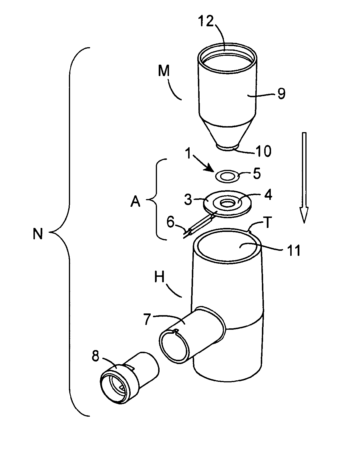
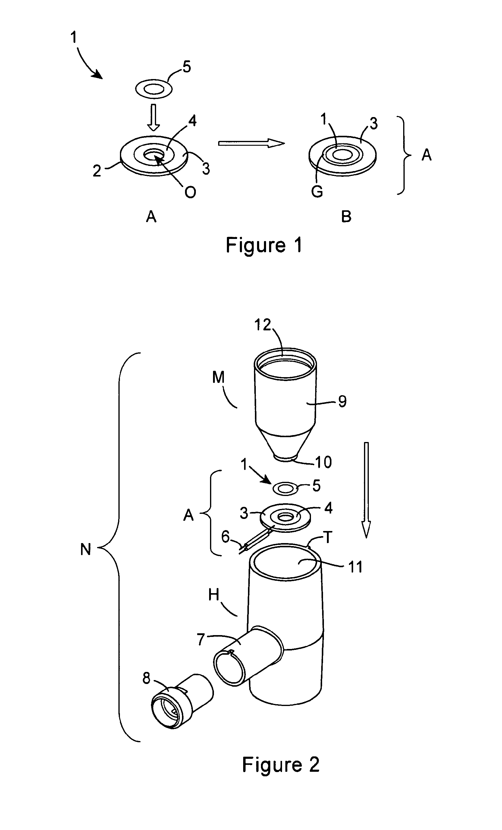
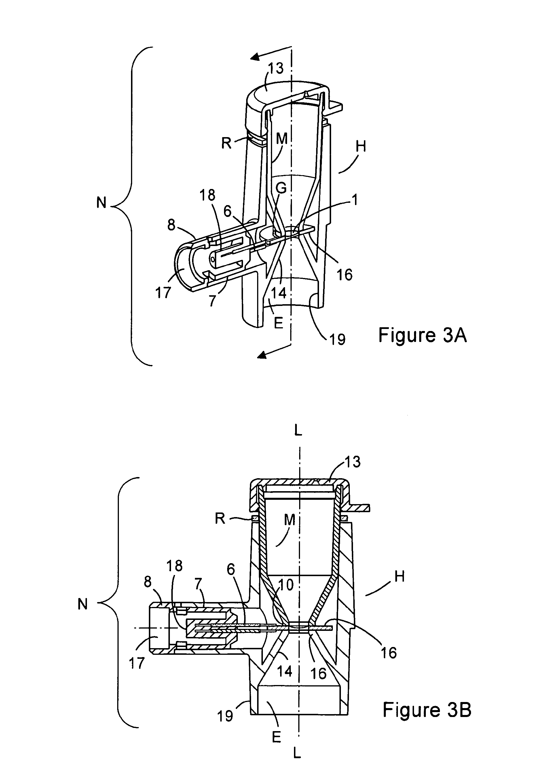
[0090]Referring now to the drawings and specifically FIGS. 1 to 5 inclusive and initially FIGS. 1A and 1B. FIG. 1A shows the individual components of a piezo ceramic actuator A according to the present invention, as illustrated generally by reference sign A. The piezo ceramic actuator A comprises a flexible nozzle / membrane plate 1 and an annular piezo ceramic body 2 (vibratable piezo ceramic body) having a centrally disposed aperture O disposed therein. The annular piezo ceramic body 2 is surface coated with a film of electrical contact material 3, except in the region about the centrally disposed aperture O which is not coated with electrical contact material 3. This forms an area of electrical contact fr...


PUM


Abstract

An aerosol generator assembly comprising a vibratable piezo ceramic body (2) having first and second opposing sides, an aperture (o) defined in the vibratable body and extending through the body from the first side to the second side and having a layer of electrical contact material on each side of the vibratable body, the vibratable body being vibratable by application of an electrical signal thereto; a vibratable member (1) with pores defined therein, the vibratable member mounted across the aperture; and an electrical contact material free-zone (4) is provided on at least one side of the body about the aperture, characterised in that the electrical contact material free-zone and the vibratable member are dimensioned so that the vibratable member is mountable directly onto the vibratable body on top thereof within the electrical contact material free-zone such that a gap area free of electrode contact material is formed between the terminating edge of the electrical contact material and the periphery of the vibratable member.

Description

FIELD OF THE INVENTION[0001]The invention relates to aerosol generators and in particular to liquid aerosol droplet generators which are often electronically controlled for example those of the piezo-based type. More particularly, the invention relates to improvements to electronic piezo-based liquid aerosol generator assemblies.BACKGROUND TO THE INVENTION[0002]There have existed for some time piezo-based aerosol generators for use in the generation of aerosolized liquids, for example, in the construction of nebulisers for aerosolization of pharmaceutical solutions for therapeutic use by delivery through aerosol inhalation to the lungs.[0003]Existing electronic piezo based aerosol generator devices typically comprise an actuator unit which generally utilises a support substrate (generally a disc-shaped metal, such as stainless steel or a brazing metal or alloy) having a central orifice adapted to accommodate a nozzle plate, which typically has a dome shaped central portion surrounde...

Claims


Application Information

Patent Timeline
Patent Type & Authority Applications(United States)
IPC IPC(8): B05B17/06
CPCA61M11/005A61M15/0085A61M15/025B05B17/0646B05B17/0676A61M2202/0468
Inventor MORAN, DECLANO'SULLIVAN, GAVAN
Owner NORTEV
Why Eureka
Try Eureka