Modular Feed Network

a module-based, feed network technology, applied in the direction of modular arrays, linear waveguide fed arrays, antennas, etc., can solve the problems of preventing simultaneous efficient alignment of the link for both channels, increasing the overall cost, and resonant configurations typically cannot achieve the requisite electromagnetic characteristics

Active Publication Date: 2013-05-16
COMMSCOPE TECH LLC
View PDF0 Cites 72 Cited by
  • Summary
  • Abstract
  • Description
  • Claims
  • Application Information

AI Technical Summary

Problems solved by technology

However, the extensive structure of a reflector dish and associated feed may require significantly enhanced support structure to withstand wind loads, which may increase overall costs.
Resonant configurations typically cannot achieve the requisite electromagnetic characteristics over the bandwidths utilized in the terrestrial point-to-point market sector, whilst travelling wave arrays typically provide a mainbeam radiation pattern which moves in angular position with frequency.
Because terrestrial point to point communications generally operate with Go/Return channels

Method used


Image

  • Modular Feed Network
  • Modular Feed Network
  • Modular Feed Network

Examples


Embodiment Construction

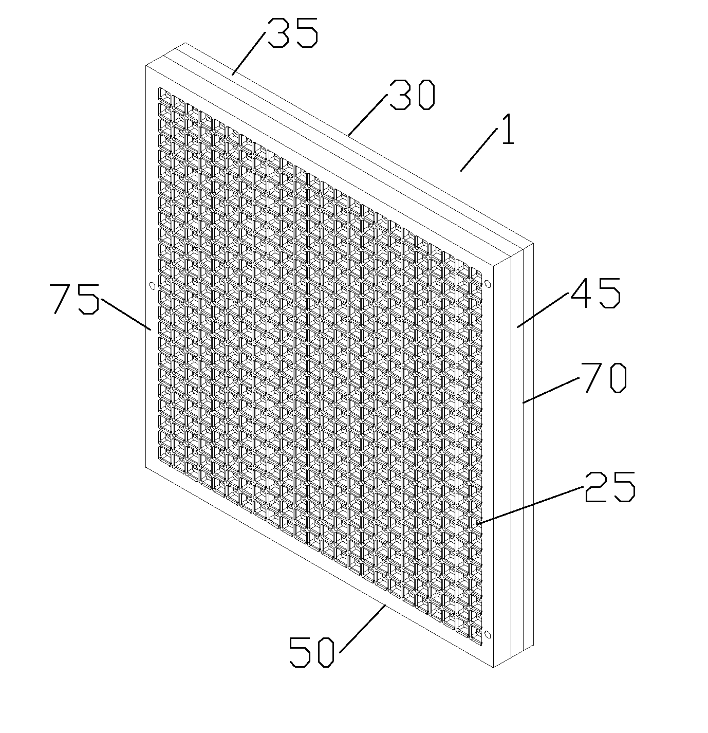
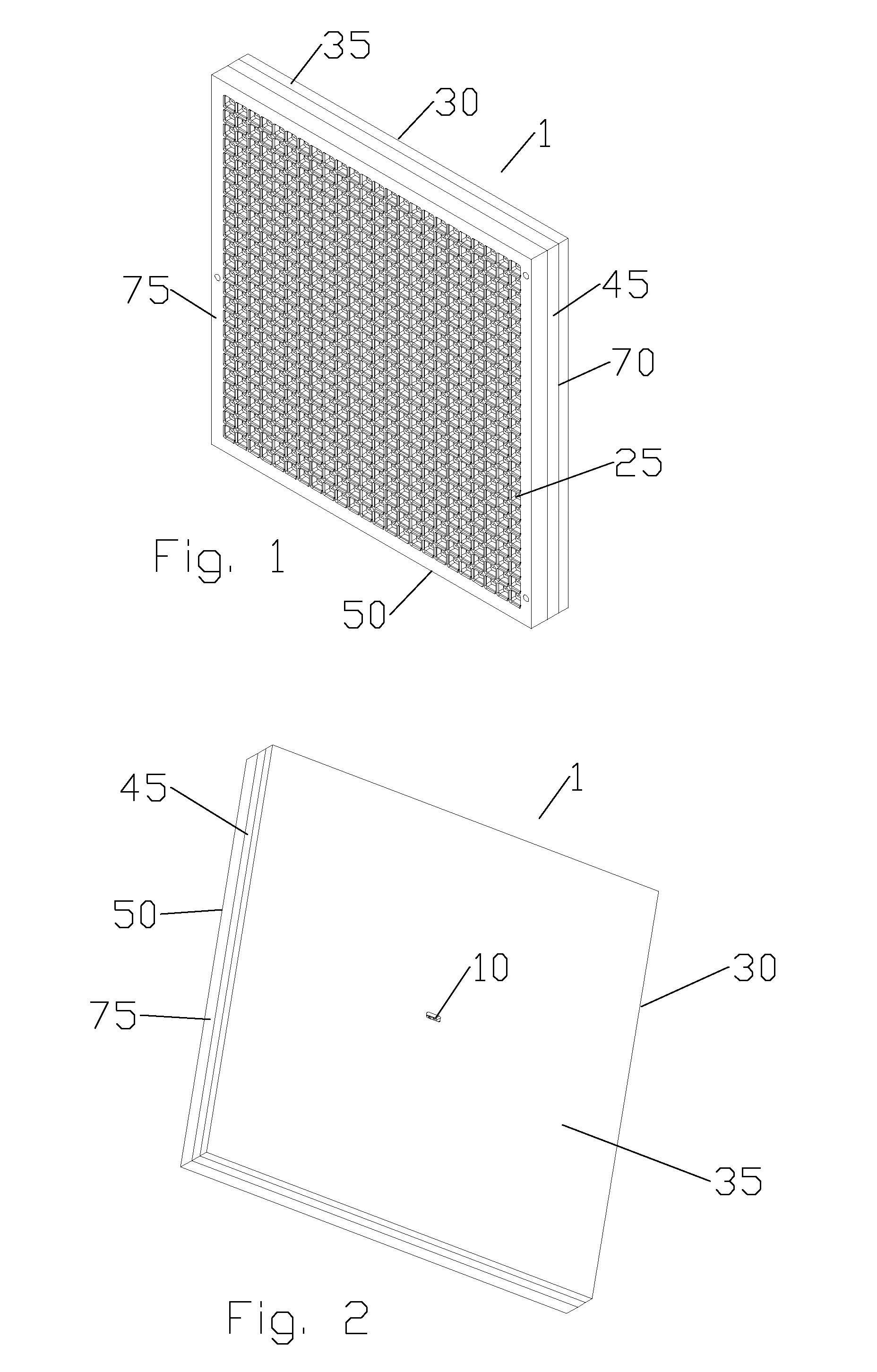
[0034]The inventors have developed a flat panel antenna utilizing a corporate waveguide network and cavity couplers provided in stacked layers. The low loss 4-way coupling of each cavity coupler significantly simplifies the requirements of the corporate waveguide network, enabling higher feed horn density for improved electrical performance. The layered configuration enables cost efficient precision mass production.

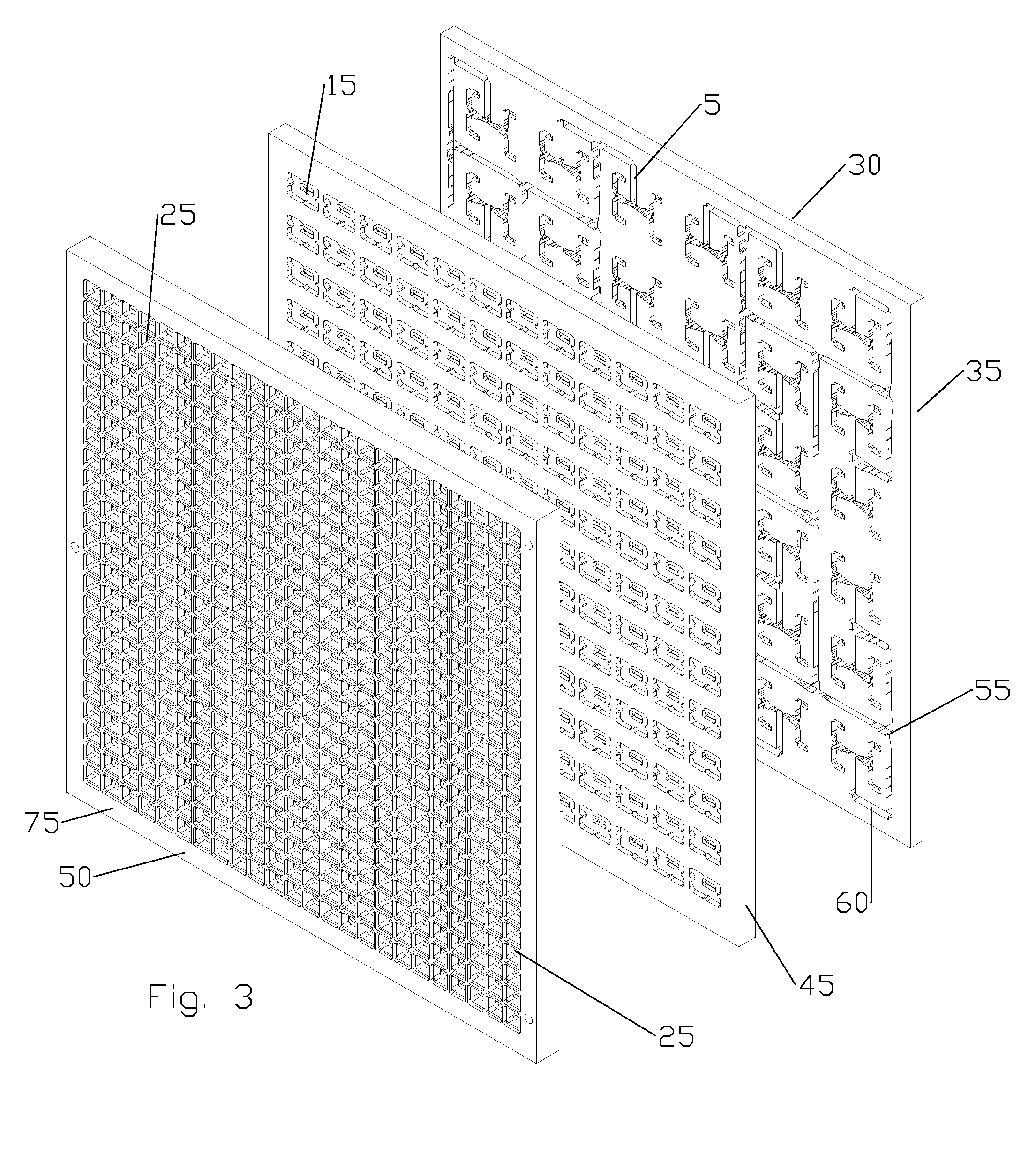
[0035]As shown in FIGS. 1-8, a first embodiment of a flat panel array antenna 1 is formed from several layers, each with surface contours and apertures, combining to form a feed horn array 4 and RF path comprising a series of enclosed coupling cavities and interconnecting waveguides when the layers are stacked upon one another.

[0036]The RF path comprises a waveguide network 5 coupling an input feed 10 to a plurality of primary coupling cavities 15. Each of the primary coupling cavities 15 is provided with four output ports 20, each of the output ports 20 coupled to a horn...


PUM

PropertyMeasurementUnit
Lengthaaaaaaaaaa

Abstract

A modular feed network is provided with a segment base provided with a feed aperture, a corner cavity at each corner and a tap cavity at a mid-section of each of two opposite sides. A segment top is provided with a plurality of output ports. The segment top is dimensioned to seat upon the segment base to form a segment pair. the segment base provided with a plurality of waveguides between cavities of the segment base. The modular feed network is configurable via a range of feed, bypass and/or power divider taps seated in the apertures and/or cavities to form a waveguide network of varied numbers of output ports by routing across one or more of the segment tops. For example, the modular feed network may comprise 1, 4 or 16 of the segment bases retained side to side.

Description

CROSS REFERENCE TO RELATED APPLICATIONS[0001]This application is a continuation-in-part of commonly owned co-pending U.S. Utility patent application Ser. No. 13 / 297,304, titled “Flat Panel Array Antenna” filed Nov. 16, 2011 by Alexander P. Thomson, Claudio Biancotto and Christopher D. Hills, hereby incorporated by reference in its entirety.BACKGROUND[0002]1. Field of the Invention[0003]This invention relates to a microwave antenna. More particularly, the invention provides a flat panel array antenna utilizing cavity coupling to simplify corporate feed network requirements.[0004]2. Description of Related Art[0005]Flat panel array antenna technology has not been extensively applied within the licensed commercial microwave point to point or point to multipoint market, where more stringent electromagnetic radiation envelope characteristics consistent with efficient spectrum management are common. Antenna solutions derived from traditional reflector antenna configurations such as prime f...

Claims


Application Information

Patent Timeline
IPC IPC(8): H01Q21/00H01P11/00
CPCH01Q21/005H01P11/00H01Q21/0043Y10T29/49016H01Q21/064H01Q21/0025H01Q21/0037H01Q21/0087
Inventor BIANCOTTO, CLAUDIOHILLS, CHRISTOPHER D.THOMSON, ALEXANDER
Owner COMMSCOPE TECH LLC
Why Eureka
Try Eureka