Temperature detection circuit and method of adjusting the same
a temperature detection circuit and temperature technology, applied in the field of temperature detection circuits, can solve the problems of difficult accurate temperature detection and expensive thermistors with less manufacturing variations, and achieve the effects of reducing accuracy, high-accuracy temperature detection, and increasing the temperature of semiconductors
- Summary
- Abstract
- Description
- Claims
- Application Information
AI Technical Summary
Benefits of technology
Problems solved by technology
Method used
Image
Examples
embodiment 1
[0028]Hereinafter, a temperature detection circuit according to the present invention will be described in detail with reference to the drawings.
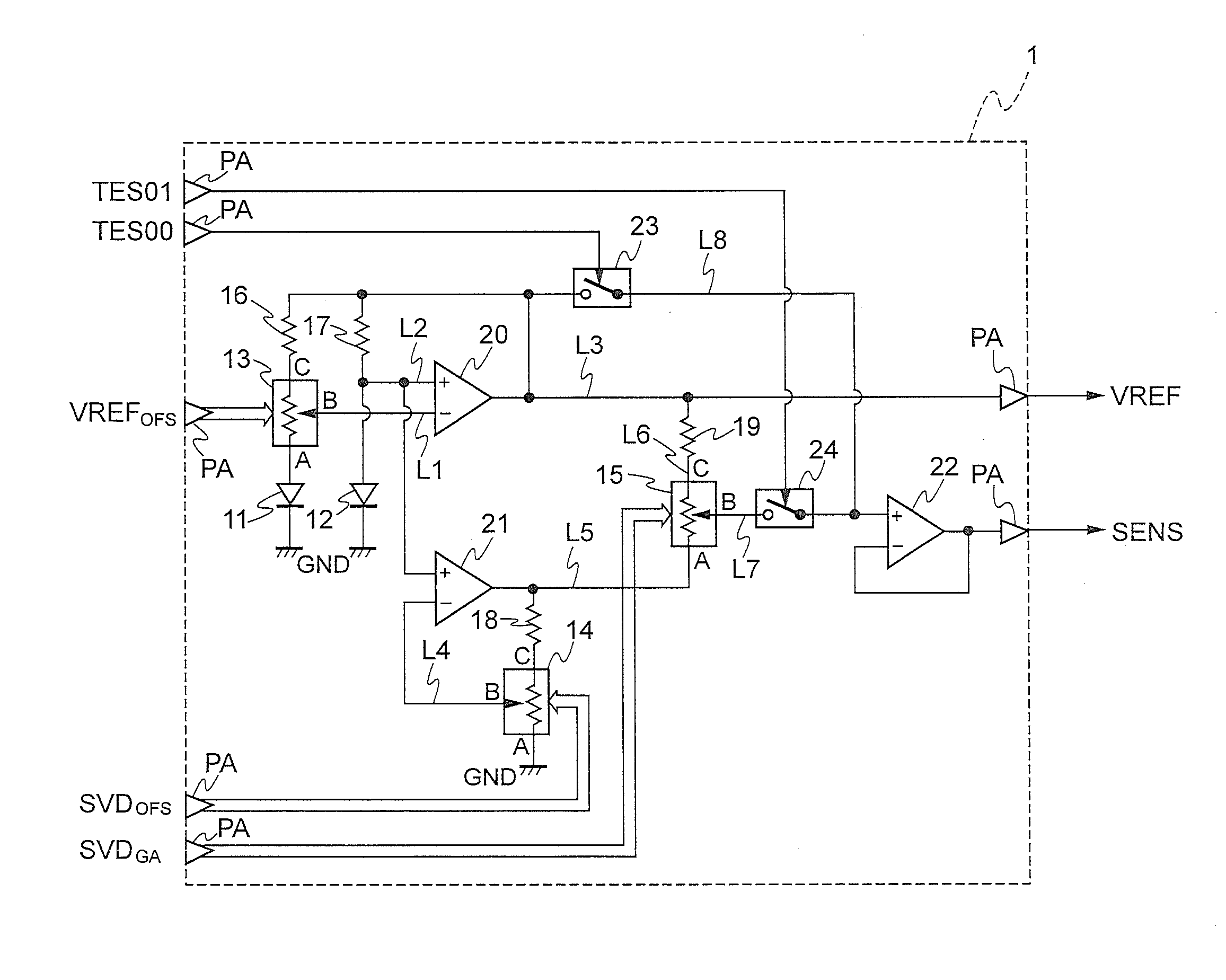
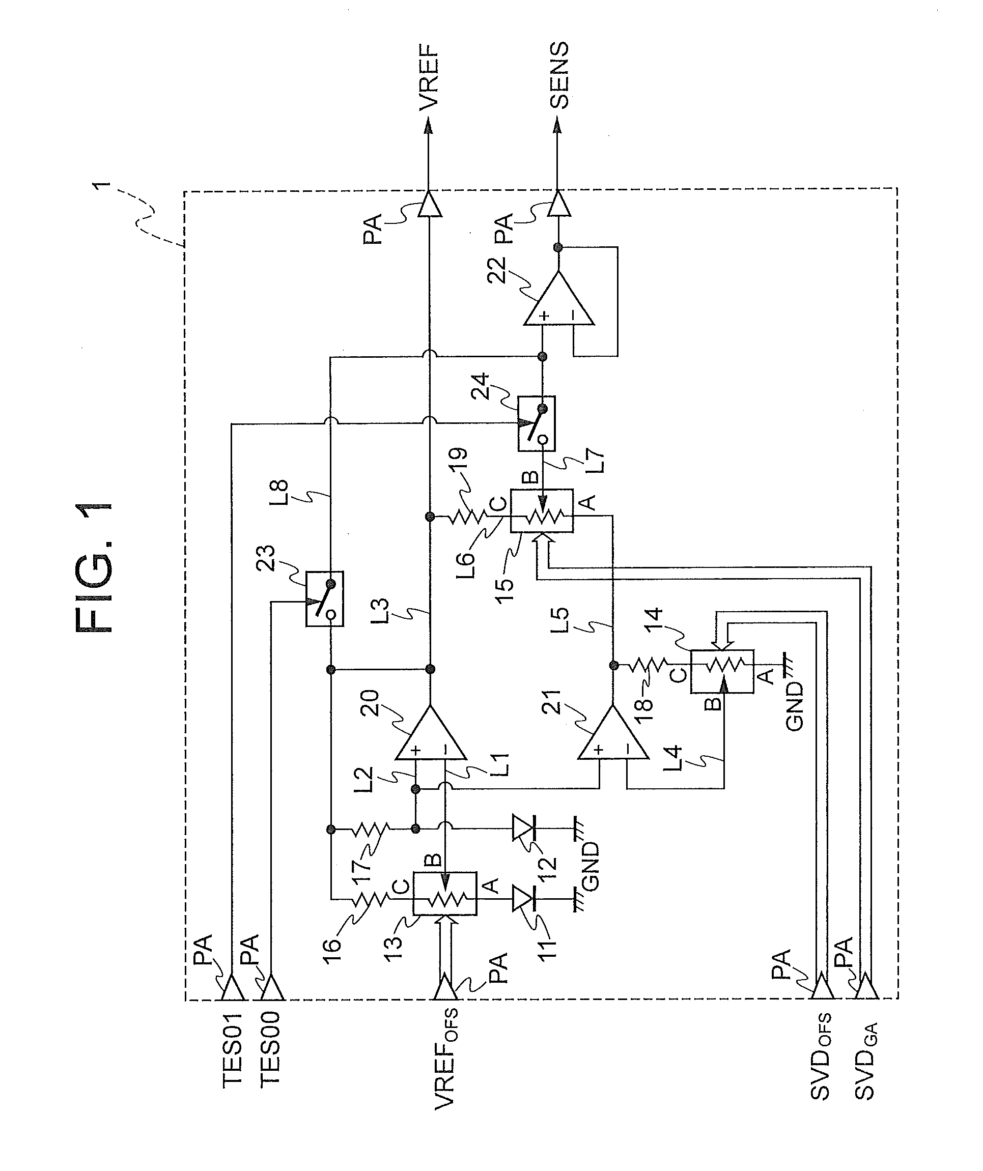
[0029]FIG. 1 is a circuit diagram showing a first embodiment of the temperature detection circuit according to the present invention.
[0030]In FIG. 1, the temperature detection circuit 1 is a so-called bandgap reference circuit which uses the band gap energy of silicon semiconductors. The temperature detection circuit 1 is constructed on a semiconductor integrated chip to detect temperature of. The temperature detection circuit 1 includes diodes 11 and 12, variable voltage dividing resistors 13 to 15, resistors 16 to 19, operational amplifiers 20 to 22, and switch elements 23 and 24.
[0031]A ground potential GND is applied to the cathode terminal of the diode 11 serving as a first diode 11. The anode terminal of the diode 11 is connected to a terminal A of the variable voltage dividing resistor 13. The terminal A of the variable voltage divid...
embodiment 2
[0064]FIG. 6 is a circuit diagram showing a second embodiment of the temperature detection circuit according to the present invention.
[0065]In FIG. 6, the temperature detection circuit 1A is a so-called bandgap reference circuit which uses semiconductor band gap energy, and is constructed on a semiconductor integrated chip to detect temperature of. The temperature detection circuit 1A includes diodes 11 and 12, variable voltage dividing resistors 13, 14, and 25, resistors 16, 18, and 26, operational amplifiers 20 to 22, and switch elements 23, 24, and 27.
[0066]A ground potential GND is applied to the cathode terminal of the diode 11 serving as a first diode. The anode terminal of the diode 11 is connected to a terminal A of the variable voltage dividing resistor 13.
[0067]The terminal A of the variable voltage dividing resistor 13 serving as a first variable voltage dividing resistor is connected to the anode terminal of the diode 11. A terminal B of the variable voltage dividing res...
PUM
 Abstract
Description
Claims
Application Information
 - R&D
- Intellectual Property
- Life Sciences
- Materials
- Tech Scout
- Unparalleled Data Quality
- Higher Quality Content
- 60% Fewer Hallucinations
Browse by: Latest US Patents, China's latest patents, Technical Efficacy Thesaurus, Application Domain, Technology Topic, Popular Technical Reports.
© 2025 PatSnap. All rights reserved.Legal|Privacy policy|Modern Slavery Act Transparency Statement|Sitemap|About US| Contact US: help@patsnap.com


