
Method for predicting sediment content of a hydroprocessed hydrocarbon product

Active Publication Date: 2013-05-16
CHEVROU USA INC
View PDF3 Cites 11 Cited by
  • Summary
  • Abstract
  • Description
  • Claims
  • Application Information

AI Technical Summary

Benefits of technology

The present invention provides a simple and cost-effective way to predict the sediment formation potential of a hydrocarbon-containing feedstock after hydroprocessing. This allows for the adjustment of refinery operation conditions to minimize fouling and design blending strategies with minimal fouling based on the feed. The method can also help quality control of new batches of feedstocks without affecting refinery operation conditions.

Problems solved by technology

These feedstocks generally contain significantly more undesirable components, especially from an environmental point of view.
Furthermore, specifications for fuels, lubricants, and chemical products, with respect to such undesirable components, are continually becoming stricter.
Consequently, such feedstocks and product streams require more severe upgrading in order to reduce the content of such undesirable components.
More severe upgrading, of course, adds considerably to the expense of processing these petroleum streams.
However, changes in pressure, temperature or concentration of the crude oil can alter the stability of the dispersion and increase the tendency of the asphaltenes to agglomerate into larger particles.
One of the problems encountered during hydroprocessing (i.e., refining) is sediment formation.
This affects the overall economy of the system since the reactor system cannot reach higher conversions.
Presently, there are only a few ways to determine sediment forming tendencies, and they are time-consuming and have a low repeatability.
This test method is time consuming, has several sources of errors and requires constant operator's attention.
It also has a limited application to those residues that can be filtered under the conditions of the method.

Method used


Image

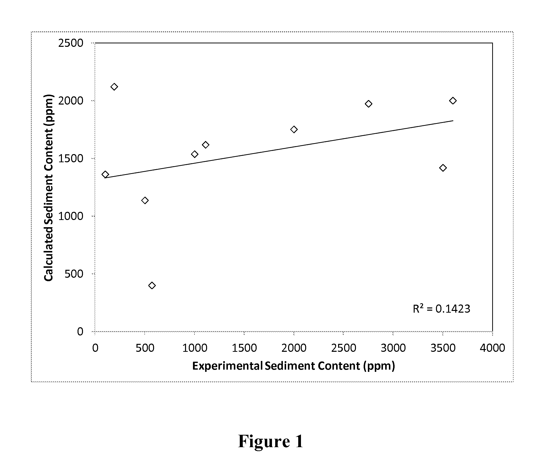
  • Method for predicting sediment content of a hydroprocessed hydrocarbon product
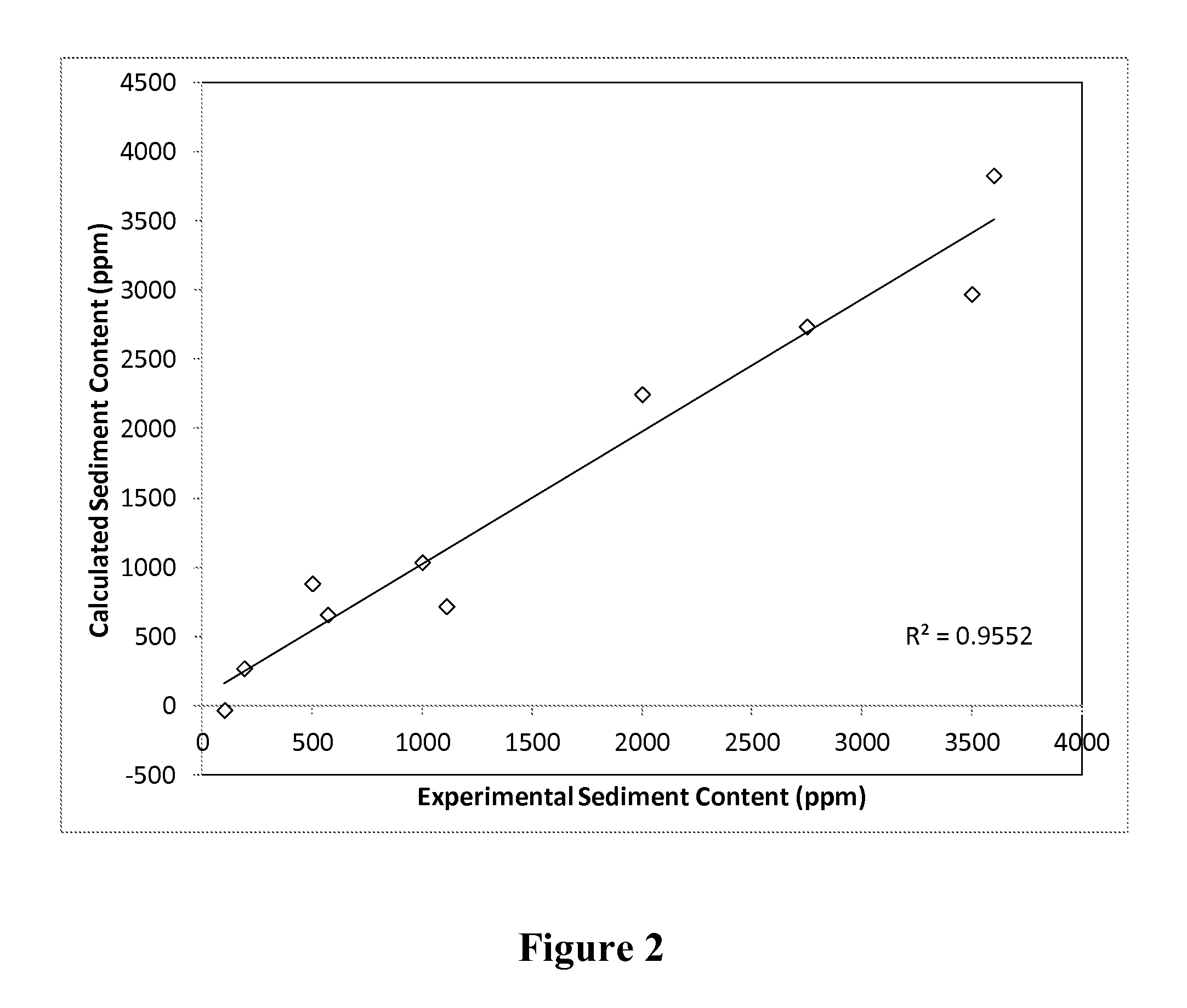
  • Method for predicting sediment content of a hydroprocessed hydrocarbon product
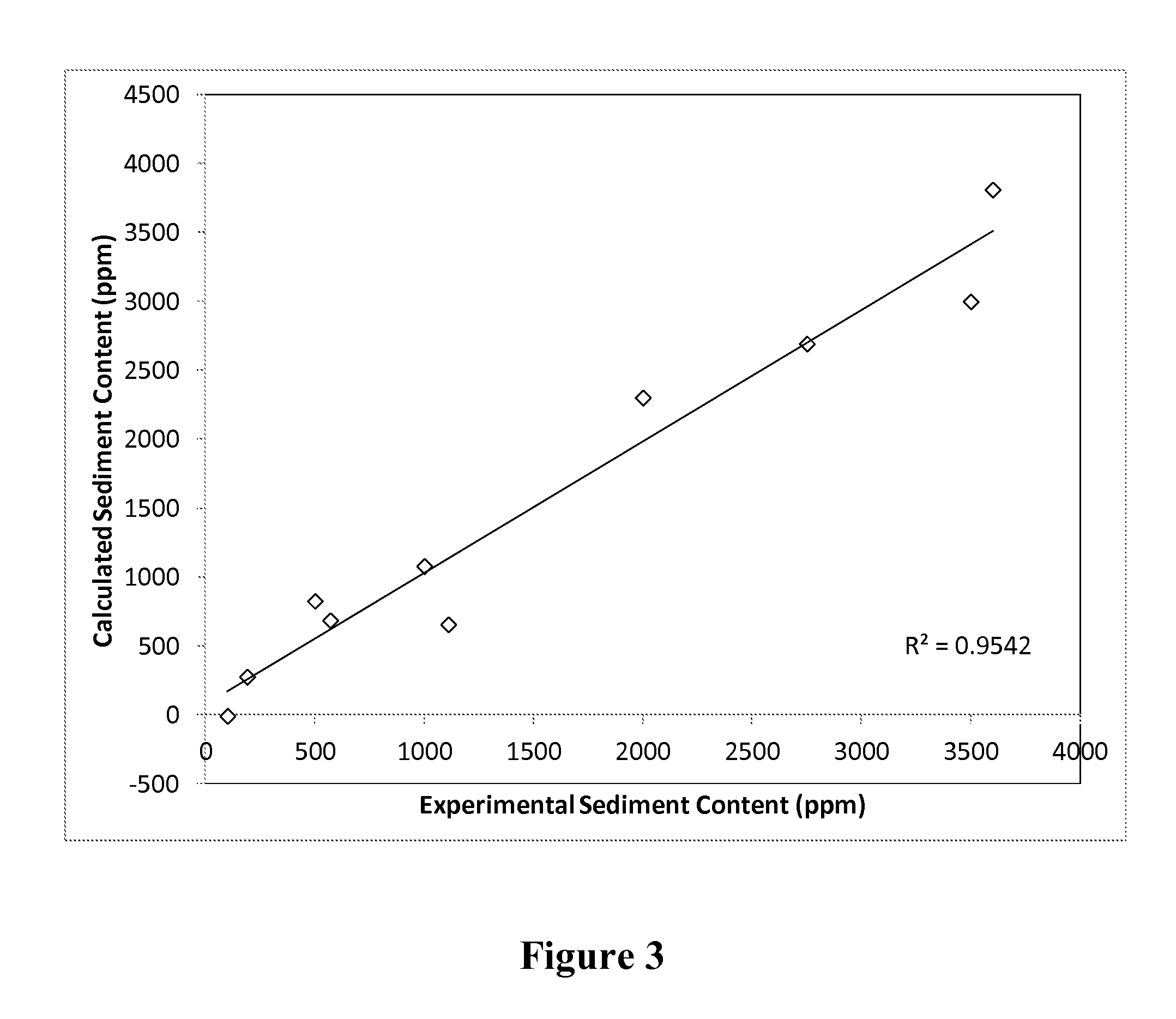
  • Method for predicting sediment content of a hydroprocessed hydrocarbon product

Examples


example 1

[0122]Several different hydrocarbon-containing feedstocks were hydroprocessed in a pilot plant using the operation conditions set forth in Table 1. The sediment content of the hydroprocessed hydrocarbon products was then measured using ASTM 4870. First, solutions of the feedstocks were prepared by dissolving 0.1000 g of the material in 10 mL of methylene chloride. Then, the solutions were injected into a separate stainless steel column packed with poly(tetrafluoroethylene) (PTFE) using n-heptane as a mobile phase. The flow rate during the whole process was 4 mL / min. The maltenes (heptane solubles) eluted from the column as the first peak around 2 minutes after the injection.

[0123]The asphaltenes remained precipitated in the column and were fractionated according to their respective solubilities by switching the mobile phase in successive steps to solvents of increasing solubility parameters: (1) 10 minutes after the injection of the sample, the mobile phase was switched to a blend o...


PUM


Abstract

Disclosed herein is a method of predicting sediment content of a hydroprocessed hydrocarbon product. The method involves: (a) precipitating an amount of asphaltenes from a liquid sample of a first hydrocarbon-containing feedstock having solvated asphaltenes therein with one or more first solvents; (b) determining one or more solubility characteristics of the precipitated asphaltenes; (c) analyzing the one or more solubility characteristics; (d) determining asphaltene content of the liquid sample from the results of analyzing the one or more solubility characteristics; (e) determining one or more asphaltene stability parameters of the liquid sample from the results of analyzing the one or more solubility characteristics; and (f) correlating the asphaltene content and one of the asphaltene stability parameters of the liquid sample with at least two operation conditions associated with a refinery to predict sediment content.

Description

BACKGROUND OF THE INVENTION[0001]1. Technical Field[0002]The present invention generally relates to a method for predicting sediment content of a hydroprocessed hydrocarbon product.[0003]2. Description of the Related Art[0004]Presently, the petroleum industry relies more heavily on relatively high boiling feedstocks derived from materials such as coal, tar sands, oil-shale, and heavy crudes. These feedstocks generally contain significantly more undesirable components, especially from an environmental point of view. For example, such undesirable components include halides, metals and heteroatoms such as sulfur, nitrogen, and oxygen. Furthermore, specifications for fuels, lubricants, and chemical products, with respect to such undesirable components, are continually becoming stricter. Consequently, such feedstocks and product streams require more severe upgrading in order to reduce the content of such undesirable components. More severe upgrading, of course, adds considerably to the e...

Claims


Application Information

Patent Timeline
IPC IPC(8): G01N30/02G06F19/00
CPCG01N33/2823G01N2030/8854G01N30/8631G01N33/2829
Inventor ROGEL, ESTRELLAOVALLES, CESARLEUNG, PAKCHEN, NAN
Owner CHEVROU USA INC
Learn More