
Modular solar receiver and solar power plant comprising at least one such receiver

a solar power plant and module technology, applied in the direction of solar heat collectors, solar heat generation using solar heat, lighting and heating apparatus, etc., can solve the problems of tube rupture, solar receivers are subject to very harsh conditions, and temperature differences

Active Publication Date: 2013-05-23
COMMISSARIAT A LENERGIE ATOMIQUE ET AUX ENERGIES ALTERNATIVES +1
View PDF2 Cites 5 Cited by
  • Summary
  • Abstract
  • Description
  • Claims
  • Application Information

AI Technical Summary

Benefits of technology

The patent text describes a system for supplying fluid to solar modules based on the amount of sunlight they receive. Cooler fluid is sent to modules in areas with high sunlight, while preheated fluid is sent to modules in areas with low sunlight. This design results in a more uniform temperature and reduced thermomechanical stress. The system is also easier to maintain, with only the defective module needing replacement instead of the entire receiver. The fluid connections are made on the rear face of the modules to maximize the surface area and prevent loss of sunlight. Overall, this design improves the efficiency and durability of solar power plants.

Problems solved by technology

On the other hand, in the case of gas, such as water vapour or air, the exchange coefficient at the panel drops, the illumination of one face of the tubes by the high solar flux gives rise to a significant difference in temperature between the illuminated face and the rear face, hence deformations potentially resulting in tube rupture.
Furthermore, the solar receiver is subject to very harsh conditions.
Indeed, it is subject to a high operating temperature, thermal gradients through the inner structure thereof due to the conductive transfer of a high heat flux, and rapid wide-ranging temperature variations, particularly during cloudy spells.
However, these expansions may be become very restrictive in the case of receivers consisting of a single large plate.
Differential expansions thus arise, which are liable to be detrimental to the receiver structure.
Moreover, the use of the receiver is not optimal.

Method used


Image

  • Modular solar receiver and solar power plant comprising at least one such receiver
  • Modular solar receiver and solar power plant comprising at least one such receiver
  • Modular solar receiver and solar power plant comprising at least one such receiver

Examples


Embodiment Construction

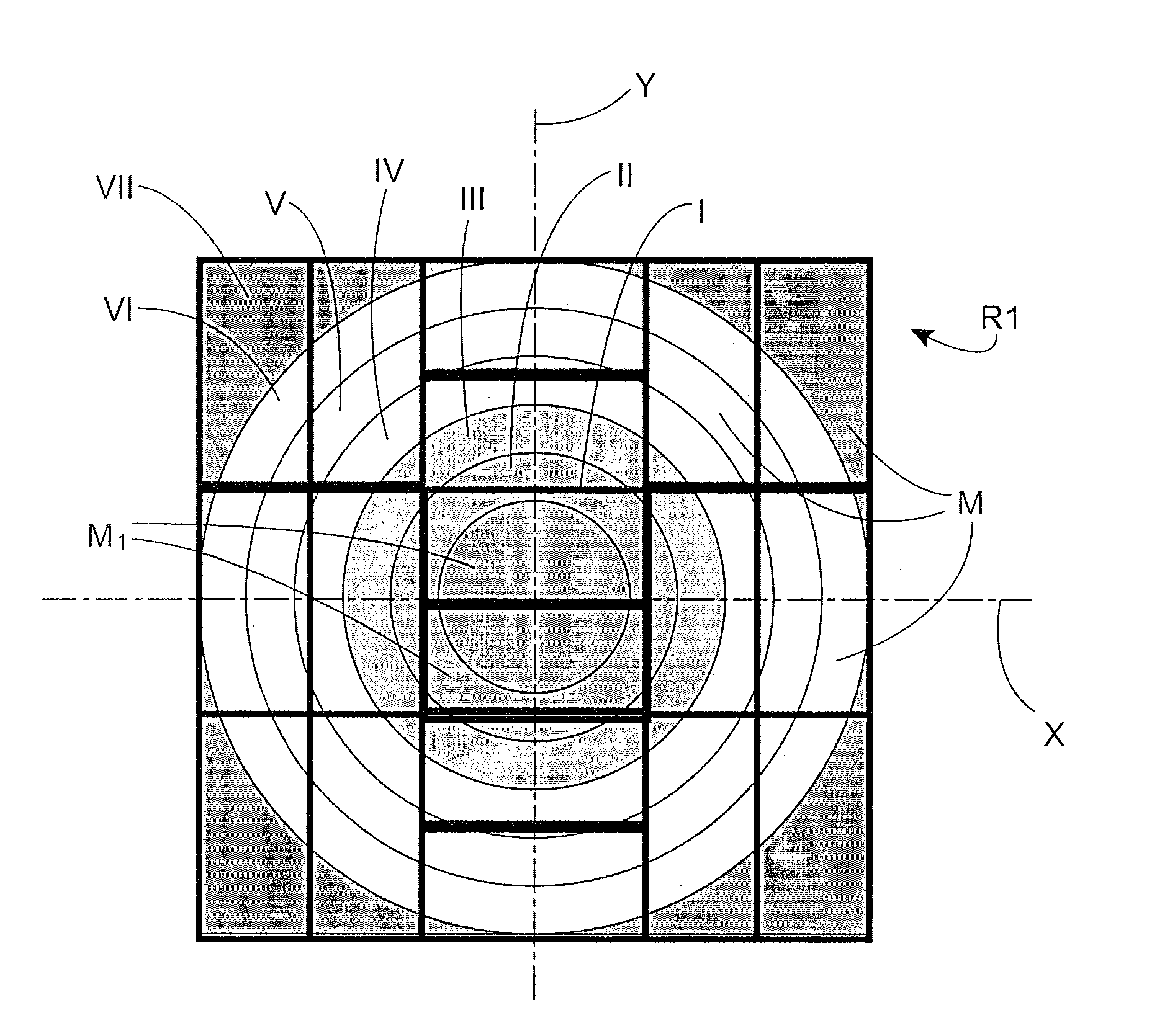
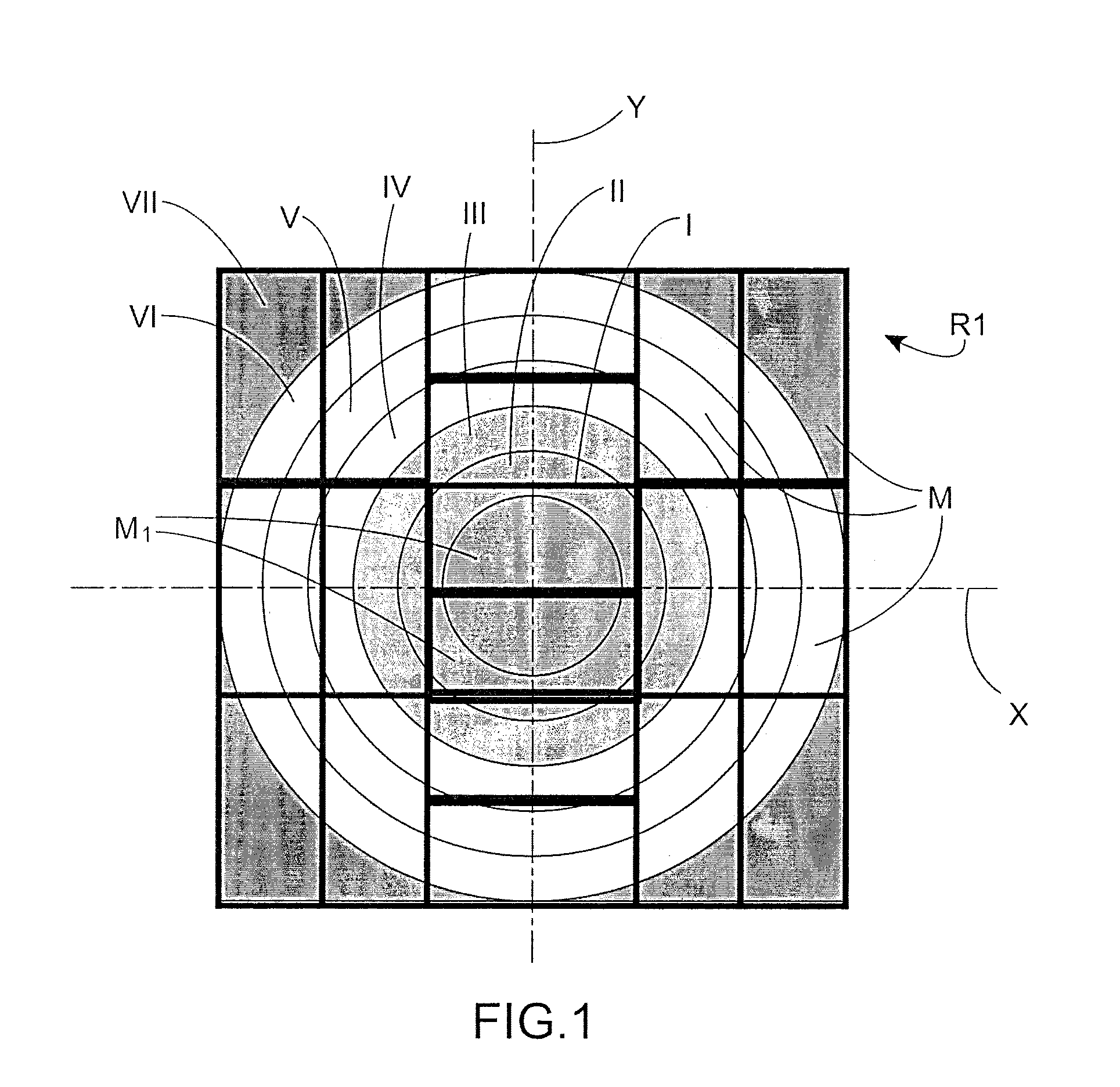
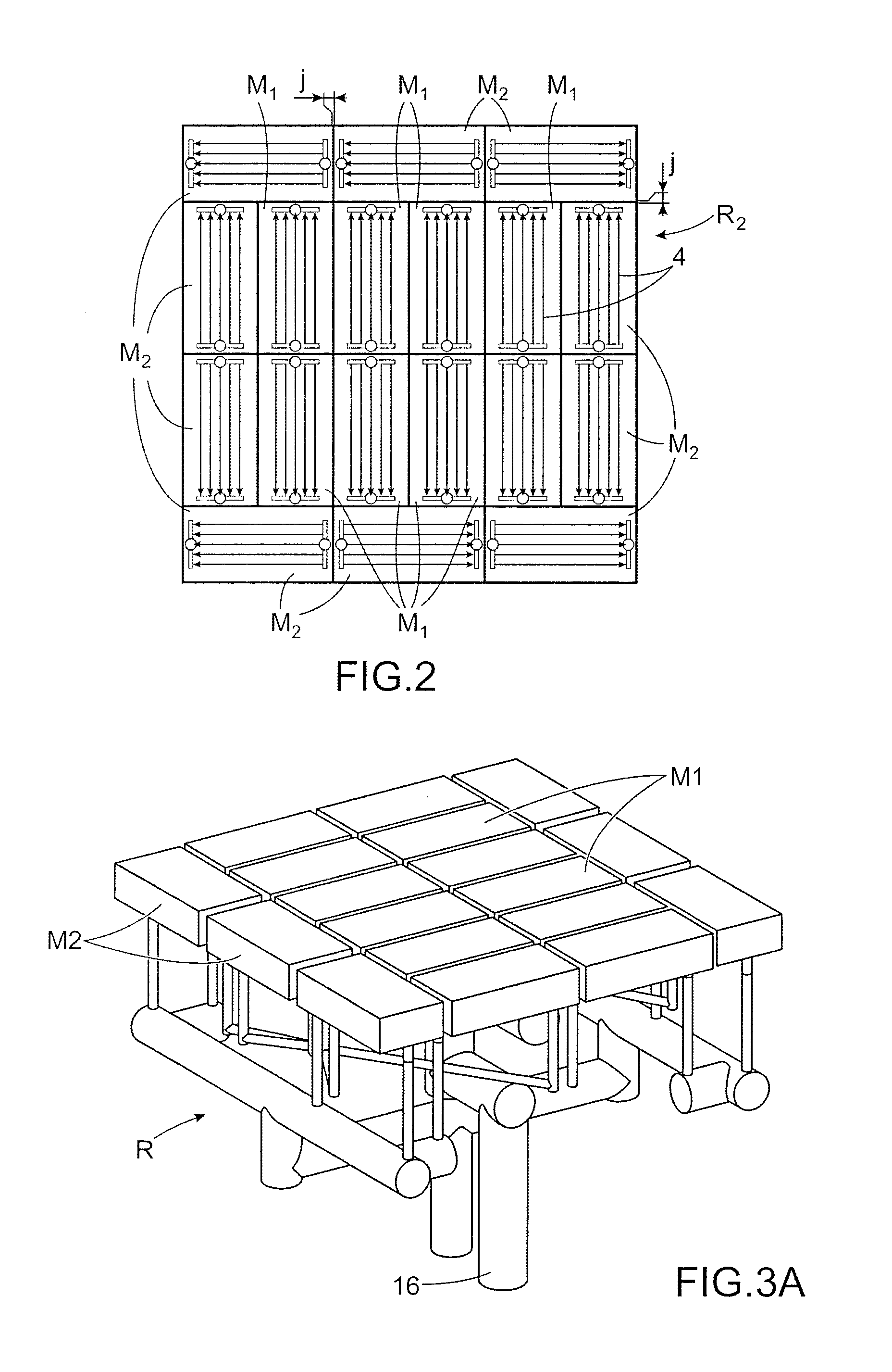
[0010]The aim mentioned above is achieved by a solar receiver consisting of a plurality of absorber modules each comprising a specific fluid circuit. The modules form a paving suitable for free expansion of each of the modules. Since the absorber modules have a smaller surface area with respect to an absorber according to the prior art, the surface of each module is subject to a more homogeneous flux. The module circuits are connected to each other.

[0011]Particularly advantageously, the fluid supply of the modules may be adapted according to the flux received. In the case of a module situated in a high-flux area, it may be supplied with cold fluid, and in the case of a module situated in a low-flux area, the module may be supplied with the fluid preheated in the module situated in the high-flux area. The temperature of the entire receiver is more homogeneous and the thermomechanical stress is reduced.

[0012]More generally, due to the modular design, any type of fluid circuit may be e...


PUM


Abstract

A solar receiver for a thermal power plant including a plurality of absorber modules, each absorber module including at least one face configured to be illuminated by a solar flux, wherein the modules are arranged side by side forming a paving. Each absorber module further includes its own fluid circuit in which a fluid to be heated by the solar flux can flow, the fluid circuits of the absorber modules being connected to one another.

Description

FIELD OF THE INVENTION AND STATE OF THE RELATED ART[0001]The present invention relates to a solar receiver and a concentrating solar power plant comprising at least one such receiver, more specifically a solar power tower.[0002]Concentrating solar thermal technology consists of using solar radiation to heat a heat transfer fluid acting as a heat source in a thermodynamic cycle. Concentration makes it possible to reach temperatures of varying levels and thus benefit from varying degrees of thermodynamic conversion efficiency.[0003]Typically, there are four categories of Concentrating Solar Power (CSP) systems: line-focus parabolic trough collectors, linear Fresnel concentrators, central receiver tower systems and mobile-focus parabolic receivers.[0004]A solar power tower particularly comprises a solar receiver receiving solar radiation transmitted by mirrors referred to as heliostats. The solar receiver is the site where the solar radiation is converted into sensible heat. It acts as...

Claims


Application Information

Patent Timeline
Patent Type & Authority Applications(United States)
IPC IPC(8): F24J2/04F24S20/20F24S23/70
CPCF22B1/006F24J2/07F24J2/1047F24J2/4636F24J2/04F24J2002/0038F24J2002/108Y02E10/41F24J2/4647F24S10/00F24S20/20F24S23/80F24S40/80F24S80/30F24S2020/10F24S2023/872Y02E10/44Y02E10/40
Inventor PRA, FRANCKCOUTURIER, RAPHAELFERRIERE, ALAINTOCHON, PATRICE
Owner COMMISSARIAT A LENERGIE ATOMIQUE ET AUX ENERGIES ALTERNATIVES
Learn More