
Method and Device for Machining a Workpiece by Means of a Laser

a technology of laser and workpiece, which is applied in the direction of laser beam welding apparatus, welding apparatus, manufacturing tools, etc., can solve the problems of material change in the irradiated area and achieve the effect of good edge quality

Inactive Publication Date: 2013-05-23
OSRAM OPTO SEMICONDUCTORS GMBH & CO OHG
View PDF9 Cites 5 Cited by
  • Summary
  • Abstract
  • Description
  • Claims
  • Application Information

AI Technical Summary

Benefits of technology

The patent text describes a method for laser machining a workpiece using a scanner or a movable displacing table. The method can be used to separate the workpiece into multiple parts along a line using the laser beam. This separation can be achieved by melting or removing material from the workpiece. The use of a nanosecond laser can produce high-quality edges with minimal slag production. The technical effects of the method include improved accuracy in positioning the laser beam and faster machining times using a scanner.

Problems solved by technology

As a result, heat can arise in or at the workpiece, which leads to a material change in the region of the irradiated area.

Method used


Image

  • Method and Device for Machining a Workpiece by Means of a Laser
  • Method and Device for Machining a Workpiece by Means of a Laser
  • Method and Device for Machining a Workpiece by Means of a Laser

Examples


Embodiment Construction

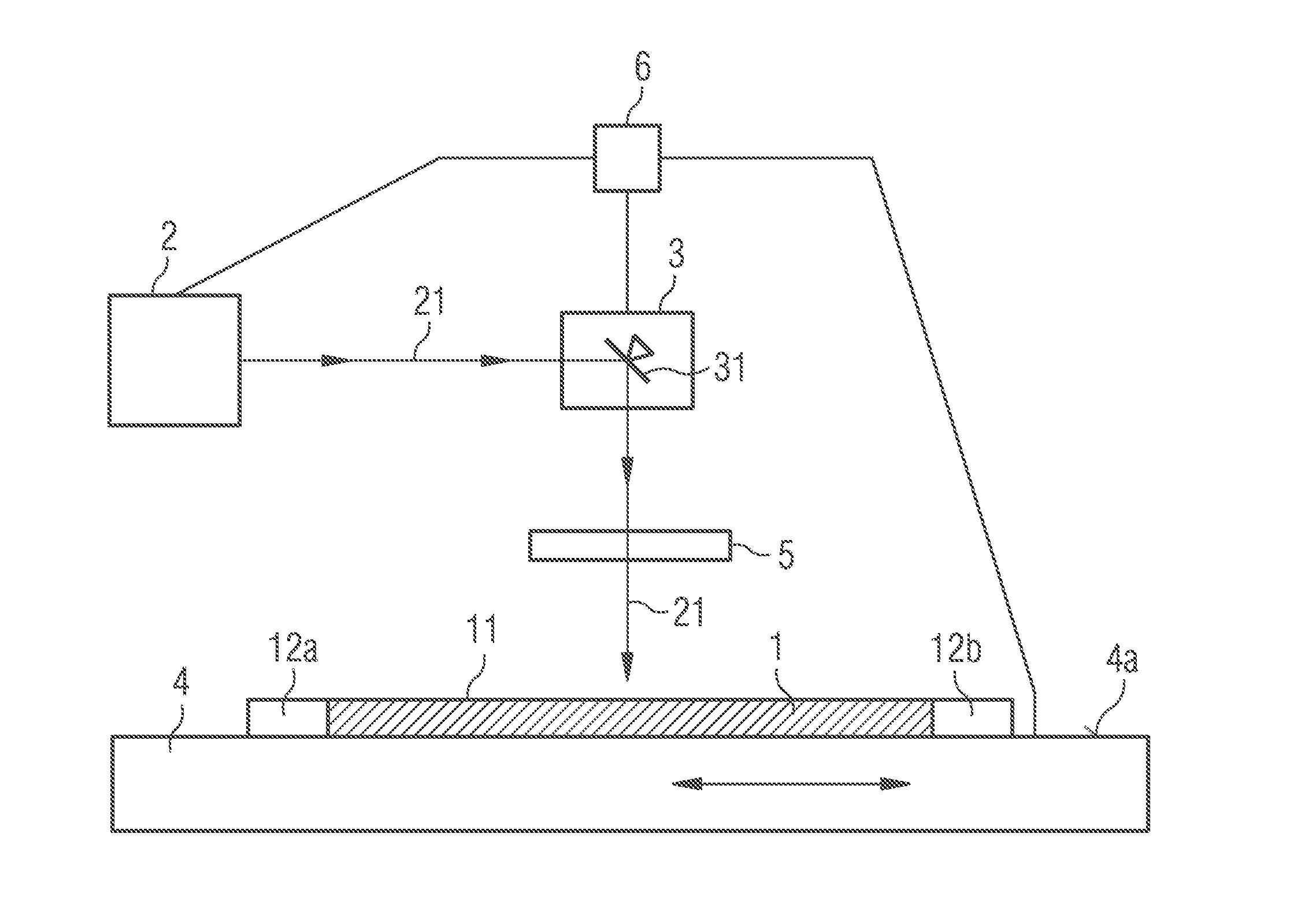
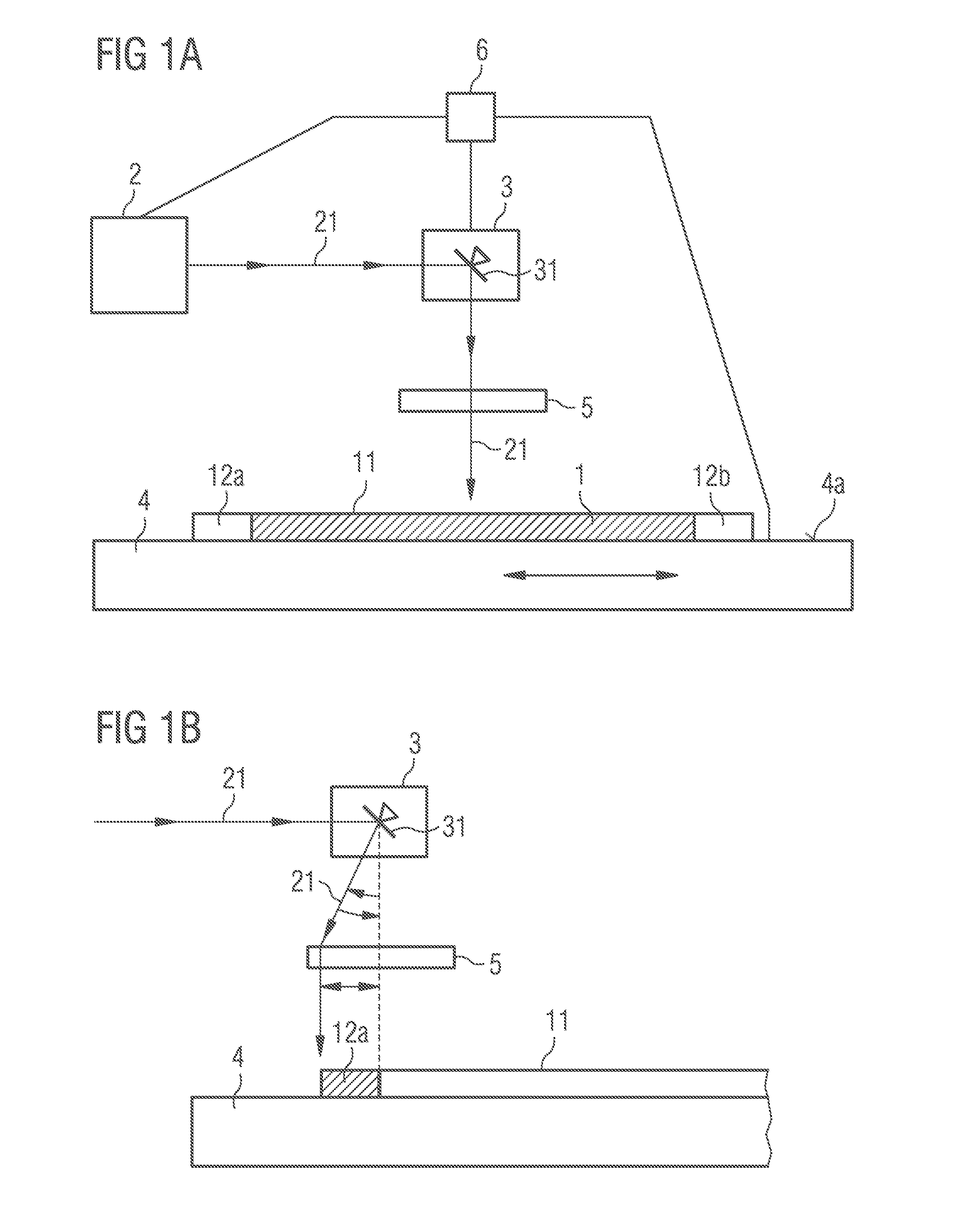
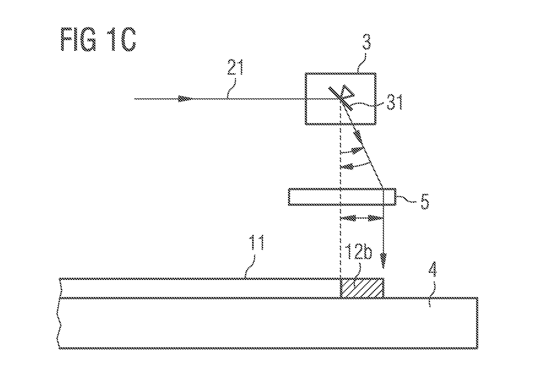
[0033]FIG. 1A shows a schematic sectional illustration of a device described here. The device comprises a laser source 2. The laser source 2 is, for example, a nanosecond laser or a picosecond laser. The device furthermore comprises an optical device 3, which is, for example, a scanner comprising a movable mirror 31.

[0034]The device furthermore comprises a displacing table, which is embodied in movable fashion. In this case, the displacing table can be moved along the arrows depicted. The workpiece 1 is arranged at the top side 4a of the displacing table 4. The workpiece 1 is a semiconductor wafer, for example, which comprises an epitaxially deposited layer sequence 13 comprising at least one active layer 14 (in this respect, also cf. FIG. 3B). The workpiece 1 is subdivided into a central region 11 and an edge region 12. By means of the movement of the displacing table 4, the workpiece 1 is also movable. For this purpose, the workpiece 1 is mechanically firmly fixed to the displacin...


PUM

PropertyMeasurementUnit
thicknessaaaaaaaaaa
thickaaaaaaaaaa
relative velocityaaaaaaaaaa

Abstract

The invention relates to a method for machining a workpiece by means of a laser, wherein a laser beam of the laser irradiates the workpiece, the laser beam remains stationary and the workpiece is moved when a central region of the workpiece is irradiated, and the laser beam and the workpiece are moved at least intermittently when an edge region of the workpiece is irradiated.

Description

[0001]This patent application is a national phase filing under section 371 of PCT / EP2011 / 055623, filed Apr. 11, 2011, which claims the priority of German patent application 10 2010 018 032.7, filed Apr. 23, 2010, each of which is incorporated herein by reference in its entirety.TECHNICAL FIELD[0002]A method for machining a workpiece by means of a laser is specified. Furthermore, a device for machining a workpiece by means of a laser is specified.SUMMARY OF THE INVENTION[0003]In accordance with at least one embodiment of the method for machining a workpiece by means of a laser, a workpiece is irradiated by a laser beam of the laser. The energy of the laser beam is preferably at least partly absorbed by the workpiece. As a result, heat can arise in or at the workpiece, which leads to a material change in the region of the irradiated area. By way of example, material can be removed from the workpiece and / or changed by means of the laser beam. That is to say that a material removal or a...

Claims


Application Information

Patent Timeline
Patent Type & Authority Applications(United States)
IPC IPC(8): B23K26/02H01L21/304
CPCB23K26/0807B23K26/02B23K26/0853B23K26/082
Inventor VEIT, THOMASJANSSEN, RUTH
Owner OSRAM OPTO SEMICONDUCTORS GMBH & CO OHG
Learn More