
Transient-state control method for a hybrid drive system for vehicles

Inactive Publication Date: 2013-05-23
INST FR DU PETROLE
View PDF7 Cites 30 Cited by
  • Summary
  • Abstract
  • Description
  • Claims
  • Application Information

AI Technical Summary

Benefits of technology

The invention integrates physical principles to reduce emissions in a hybrid drive system. Using models of physical phenomena involved in emissions production, the method calculates torque trajectories and reduces transient emissions, such as NOx, while maintaining fuel efficiency gains. This method is complementary to existing strategies and allows for uncoupling of static and transient objectives in managing hybrid vehicles.

Problems solved by technology

Indeed, emissions from current engines are highly sensitive to operating deviations.
In the case of a hybrid vehicle equipped with a diesel engine, the problem is twofold.
During gear ratio change phases, injection cut-off necessarily leads to a decrease in the richness at the exhaust.
Burnt gas availability at the intake is therefore limited when injection is restored upon acceleration.
Accounting for the transient part therefore is an important issue regarding engine control.
However, although these energy supervisors make it possible to manage the static states of the hybrid drive system, they are not suited for the management of transient states.
This hypothesis is acceptable if the engine torque is considered but it is wrong if the emissions are considered.
However, this type of empirical strategy does not allow finding the optimum trajectory and adjustment of the gradient slope depends on the engine, its calibration and the drive mode.

Method used


Image

  • Transient-state control method for a hybrid drive system for vehicles
  • Transient-state control method for a hybrid drive system for vehicles
  • Transient-state control method for a hybrid drive system for vehicles

Examples


application example

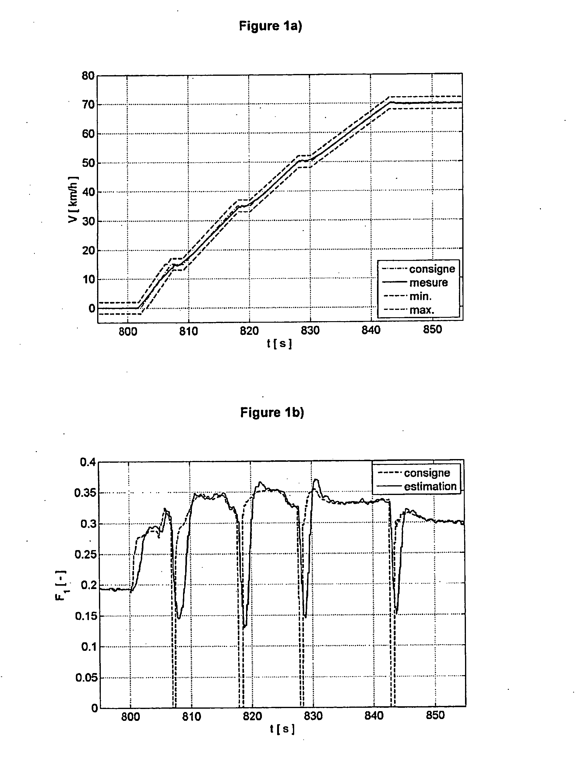
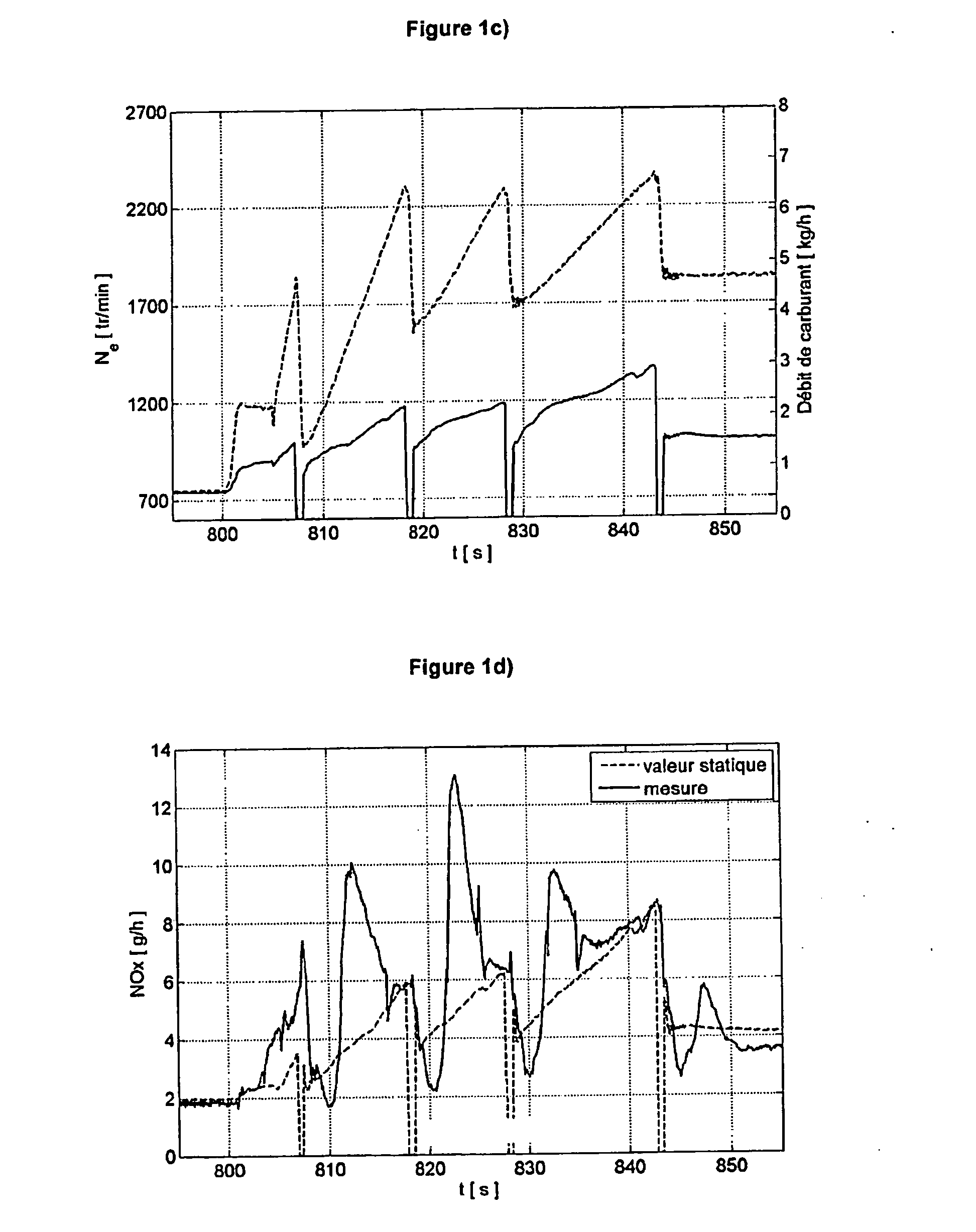
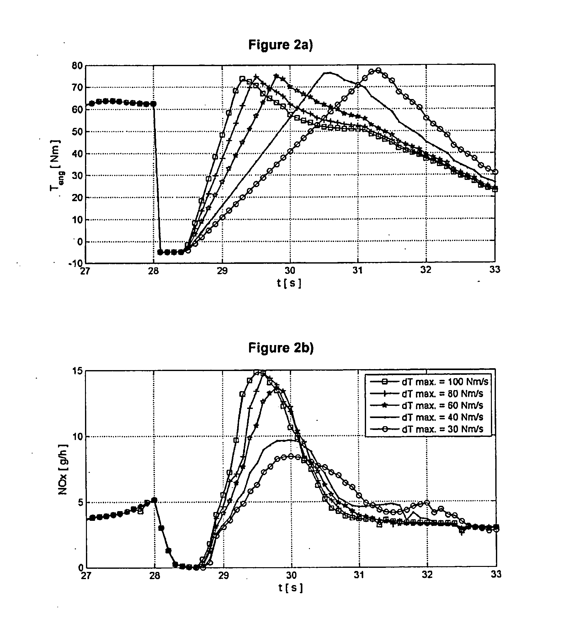
[0143]The results presented in this part are obtained from simulations of a diesel hybrid vehicle with a parallel architecture. The diesel engine is equipped with a burnt gas recirculation system. The thermal engine model is a physical model that can predict emissions and, in particular, NOx emissions. Such a model is for example described in the following document:[0144]R. Lebas, G. Mauvio, F. Le Berr & A. Albrecht, “A Phenomenological Approach to Model Diesel Engine Combustion and In-Cylinder Pollutant Emissions Adapted to Control Strategy, Proceedings of the IFAC workshop on engine and powertrain control, simulation and modeling”, Rueil-Malmaison, France, 30 Nov.-2 Dec. 2009.

[0145]This model has been calibrated from tests carried out on a Euro 6 diesel engine. The strategy of emissions limitation under transient conditions has been coupled with a static energy supervisor whose principle is based on optimal control. It is presented in the aforementioned document:[0146]O. Grondin, ...


PUM


Abstract

The invention relates to a method of controlling a hybrid drive system having at least one electric machine and at least one diesel engine. The invention corrects the static torque setpoint Teng,ssp of the diesel engine and is performed in transient state as follows: constructing a nitrogen oxides (NOx) emission model allowing estimation of the emissions of the diesel engine as a function of torque Teng of the diesel engine; calculating a dynamic NOx emission setpoint NOxsp from the NOx emission model and from the static torque setpoint Teng,ssp; determining a dynamic torque setpoint of the diesel engine Tengsp from NOx emission setpoint NOxsp; determining a dynamic torque setpoint of the electric machine Tmotsp as a function of the static torque setpoint Tpwtsp of the drive system and of the dynamic torque setpoint of the diesel engine TengspI and applying the dynamic torque setpoints to the drive system.

Description

CROSS-REFERENCE TO RELATED APPLICATION[0001]Reference is made to French patent application Ser. No. 11 / 03.497, filed on Nov. 17, 2011, which application is incorporated herein by reference in its entirety.BACKGROUND OF THE INVENTION[0002]1. Field of the Invention[0003]The present invention relates to an engine control and more particularly to the transient-state control of a hybrid drive system for vehicles, in order to reduce emissions in a hybrid vehicle comprising at least one electric machine and at least one thermal engine for driving the vehicle.[0004]2. Description of the Prior Art[0005]Accounting for emissions in transient state (generated by the change from one steady-state operating point to another steady-state operating point) from an internal-combustion engine is a very important objective. Indeed, emissions from current engines are highly sensitive to operating deviations. Furthermore, future type approval driving cycles will impose more transient phases. In the case o...

Claims


Application Information

Patent Timeline
IPC IPC(8): F02D45/00B60L50/16
CPCF02D45/00Y02T10/6286B60W10/08B60W20/00F02D41/1462F02D41/1497F02D2250/18F02D2250/36B60W20/1082Y02T10/84B60Y2400/432B60W30/1882B60W2510/0676B60W2710/0644B60W2710/0666B60W20/10Y02T10/54B60W10/06B60W20/16Y02T10/40Y02T10/62B60W2510/0638B60W20/15
Inventor THIBAULT, LAURENTGRONDIN, OLIVIERCORDE, GILLESQUEREL, CAROLEMOULIN, PHILIPPE
Owner INST FR DU PETROLE
Learn More