Thermally conductive sheet and process for producing same

a technology of thermal conductivity and thermal insulation, which is applied in the field of thermal insulation sheets, can solve the problems of inability to effectively utilize the superior thermal conductivity the method of increasing the filling rate of the inorganic insulation layer has limitations, and the flexibility is lowered, so as to achieve low, reduce the thermal resistance, and high thermal conductivity

Active Publication Date: 2013-05-30
DEXERIALS CORP
View PDF6 Cites 30 Cited by
  • Summary
  • Abstract
  • Description
  • Claims
  • Application Information

AI Technical Summary

Benefits of technology

[0021]The present invention makes it possible to solve the above-mentioned various conventional problems, and also to achieve the above-mentioned object, and since cut surfaces with low surface roughness are obtained, reduced thermal resistance is obtained on the interfaces so that it is

Problems solved by technology

However, when the filling rate of the inorganic filler is increased, the flexibility is lowered, or spilled powder might occur because of the high filling rate of the inorganic filler, this method for increasing the filling rate of an inorganic filler has a limitation.
However, in the case when, after having been molded, a cured object having been subjected to a curing process is sliced into a desired thickness, since the cured object having flexibility is sliced while be

Method used


Image

  • Thermally conductive sheet and process for producing same
  • Thermally conductive sheet and process for producing same
  • Thermally conductive sheet and process for producing same

Examples


example 1

Production of Thermally Conductive Sheet

[0106]To an addition reaction-type liquid-state silicone resin of a two-liquid type prepared by mixing 18.8% by volume of a silicone A liquid (organopolysiloxane having a vinyl group) and 18.8% by volume of a silicone B liquid (organopolysiloxane having an H—Si group) were added to be dispersed therein alumina particles (average particle size: 3 μm, Alumina DAW03, spherical shape, made by Denki Kagaku Kogyo Kabushiki Kaisha) (42.3% by volume) and pitch-based carbon fibers (average major axis length: 150 μm, average minor axis length: 8 μm, Raheama R-A301, made by Teijin Ltd.) (20.1% by volume) so that a silicone resin composition was prepared.

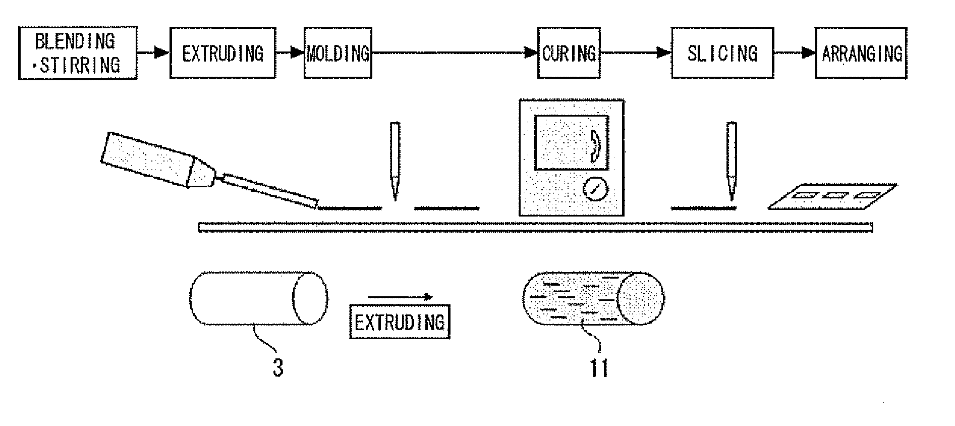
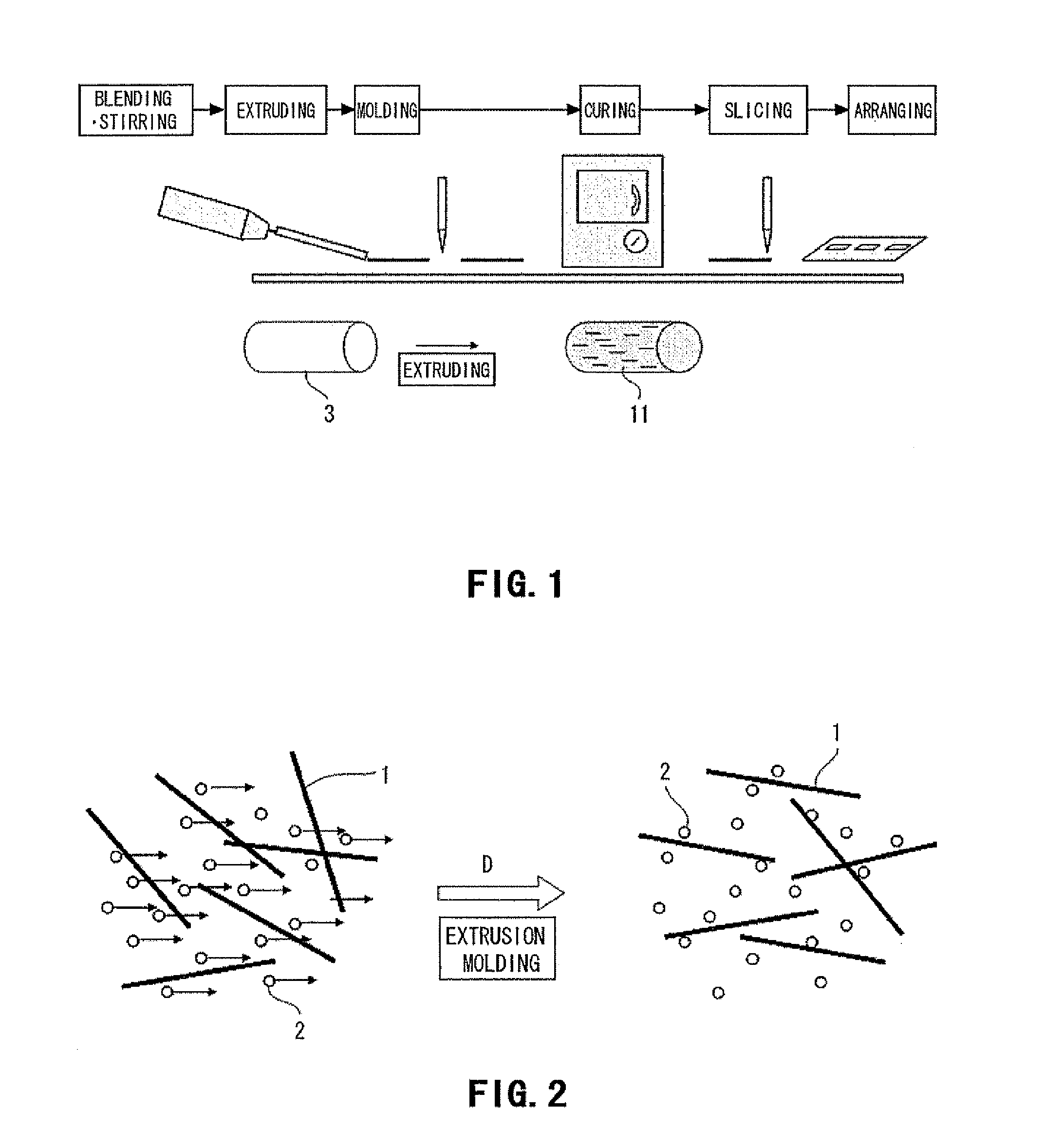
[0107]The resulting silicone resin composition was extrusion-molded into a mold 3 (hollow column shape) by using an extruder so that a silicone molded product was formed. A slit (extrusion outlet shape: flat plate) was formed on the extrusion outlet of the extruder.

[0108]The resulting silicone molded prod...

example 2

Production of Thermally Conductive Sheet

[0111]The same processes as those of example 1 were carried out except that in example 1, the alumina particles (average particle size: 3 μm, Alumina DAW03, spherical shape, made by Denki Kagaku Kogyo Kabushiki Kaisha) were changed to alumina particles (average particle size: 5 μm, Alumina DAW05, spherical shape, made by Denki Kagaku Kogyo Kabushiki Kaisha) so that a thermally conductive sheet of example 2 having a square shape of 15 mm in longitudinal length and 15 mm in lateral length with a thickness of 0.5 mm was formed.

example 3

Production of Thermally Conductive Sheet

[0112]The same processes as those of example 1 were carried out except that in example 1, the alumina particles (average particle size: 3 μm, Alumina DAW03, spherical shape, made by Denki Kagaku Kogyo Kabushiki Kaisha) were changed to alumina particles (average particle size: 10 μm, Alumina DAW10, spherical shape, made by Denki Kagaku Kogyo Kabushiki Kaisha) so that a thermally conductive sheet of example 3 having a square shape of 15 mm in longitudinal length and 15 mm in lateral length with a thickness of 0.5 mm was formed.


PUM

PropertyMeasurementUnit
Fractionaaaaaaaaaa
Angleaaaaaaaaaa
Angleaaaaaaaaaa

Abstract

A thermally conductive sheet has cut surfaces with low surface roughness and hence shows reduced thermal resistance at the interfaces, and high thermal conductivity in the thickness direction. Thus, the thermally conductive sheet can be interposed between any of various heat sources and a radiation member. The process for producing the thermally conductive sheet includes at least: an extrusion molding step in which a thermally conductive composition containing a polymer, an anisotropic thermally conductive filler, and a filler is extruded with an extruder to thereby mold an extrusion-molded product in which the anisotropic thermally conductive filler has been oriented along the extrusion direction; a curing step in which the extrusion-molded product is cured to obtain a cured object; and a slicing step in which the cured object is sliced into a given thickness with an ultrasonic cutter in the direction perpendicular to the extrusion direction.

Description

FIELD OF THE INVENTION[0001]This invention relates to a thermally conductive sheet and a process for producing such a thermally conductive sheet. The present application asserts priority rights based on JP Patent Application 2010-138334 and JP Patent Application 2010-138417 filed in Japan on Jun. 17, 2010, as well as JP Patent Application 2011-79976 filed in Japan on Mar. 31, 2011. The total contents of disclosure of the patent applications of the senior filing date are to be incorporated by reference into the present application.BACKGROUND OF THE INVENTION[0002]Along with higher performances achieved in electronic apparatuses, semiconductor elements with a higher density and highly packaged semiconductor elements have been developed. In response to this trend, it becomes essential to more efficiently radiate heat generated from electronic parts forming electronic apparatuses. In order to allow the semiconductor to radiate heat efficiently, the semiconductor is attached to a heat si...

Claims


Application Information

Patent Timeline
IPC IPC(8): C08K3/22C08L83/04B29C48/07B29C48/08B29C48/91
CPCC08J5/18Y10T428/24355C08J2383/04C08J2383/05C08J2383/07C08K2201/001C08K3/04C08G77/12C08G77/20C08K5/56C08L83/14C08K2003/2227H01L23/3737Y10T428/268Y10T428/24488Y10T428/24C08K7/06C08L83/04C08K3/22B29D7/01B29L2007/00B29L2031/18C08K2201/005C08K7/18C08L2205/025H01L2924/0002B26D3/28B29K2995/0013B29K2509/00B29K2995/0044B29C47/0066B29K2883/00B29K2995/0073B26D1/08B26D7/086B29C47/0004B29C47/0021B29C35/02B29C47/1027B29C47/8805Y10T428/24777C08L83/00H01L2924/00H01L24/27H01L24/29H01L24/83H01L2224/2929H01L2224/293H01L2224/29386H01L2224/29393H01L2224/29499H01L2224/8385B29C48/07B29C48/08B29C48/91B29C48/288B29C48/0022B29C48/022C08K3/00H01L23/36B29C70/62B29C70/14
Inventor USUI, HIROYUKIARAMAKI, KEISUKE
Owner DEXERIALS CORP
Why Eureka
Try Eureka