Process for adjusting the relative position of a first and a second piece of a mechanical assembly

Active Publication Date: 2013-06-13
THE SWATCH GRP RES & DEVELONMENT LTD
View PDF12 Cites 2 Cited by
  • Summary
  • Abstract
  • Description
  • Claims
  • Application Information

AI Technical Summary

Benefits of technology

The invention provides a simple and precise method to adjust the position of a second piece of material in relation to a first piece. This becomes possible because amorphous metals have the ability to soften when heated and become easier to move. By controlling the temperature, the viscosity of the fixture can be reduced, making it easier to move the second piece and achieve a precise position. The adjustment process is thus simplified.

Problems solved by technology

Now, if the pallets of the anchor are not positioned properly, the pulses between the pallets of the anchor and the escape wheel are not perfect and losses occur, thus affecting the efficiency of the escapement and therefore the precision of the watch.
However, the quality of gum lacquer fluctuates greatly from one batch to another, which makes repositioning a delicate operation.
Moreover, since the viscosity of gum lacquer is difficult to control and as it is difficult to control the volume of glue deposited, an overflow of the gum often occurs, which results in possibly unacceptable aesthetic flaws.
Moreover, since gum lacquer is an organic material, it is subject to aging and consequently the fixture of the pallet can be weakened.
However, these two solutions are also problematic, since to have any chance of soldering a ceramic or silicon or mineral material, it is necessary to use reactive brazing / soldering, which must be conducted at a relatively high temperature (generally above 700° C.) and in a neutral atmosphere or in high vacuum.
This results in very long assembly cycles and risks of breakage / cracking of the material are possible.

Method used


Image

  • Process for adjusting the relative position of a first and a second piece of a mechanical assembly
  • Process for adjusting the relative position of a first and a second piece of a mechanical assembly
  • Process for adjusting the relative position of a first and a second piece of a mechanical assembly

Examples


first embodiment

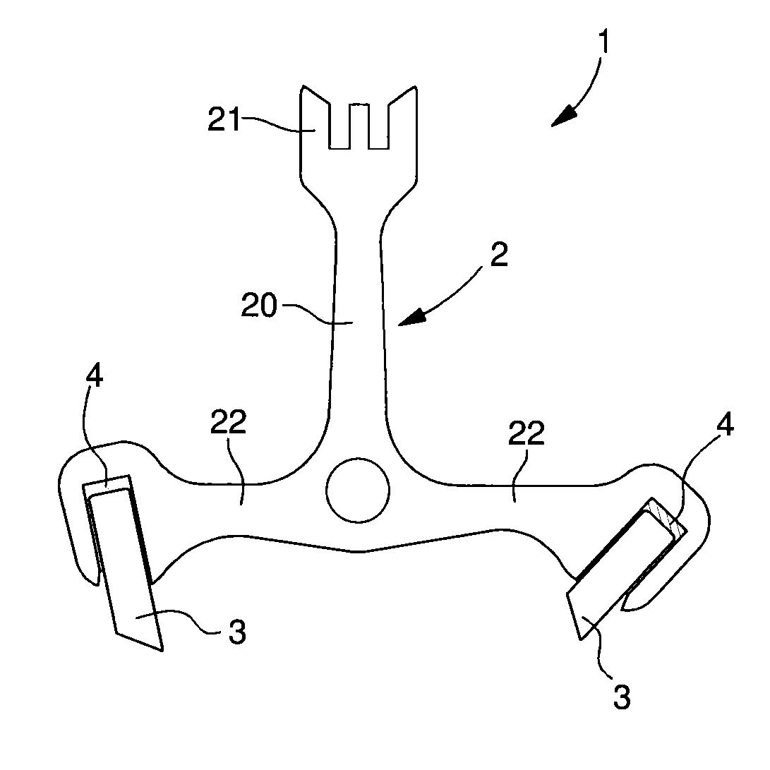
[0030]In the present invention the joint 4 is made of a first material, which is an at least partially amorphous material comprising at least one metallic element. This first material can be an at least partially amorphous metal alloy. This metallic element can be a precious metal element such as gold, platinum, palladium, rhenium, ruthenium, rhodium, silver, iridium or osmium. An at least partially amorphous material is understood to be a material that is able to solidify at least partially in amorphous phase. Said first material is preferably completely amorphous.

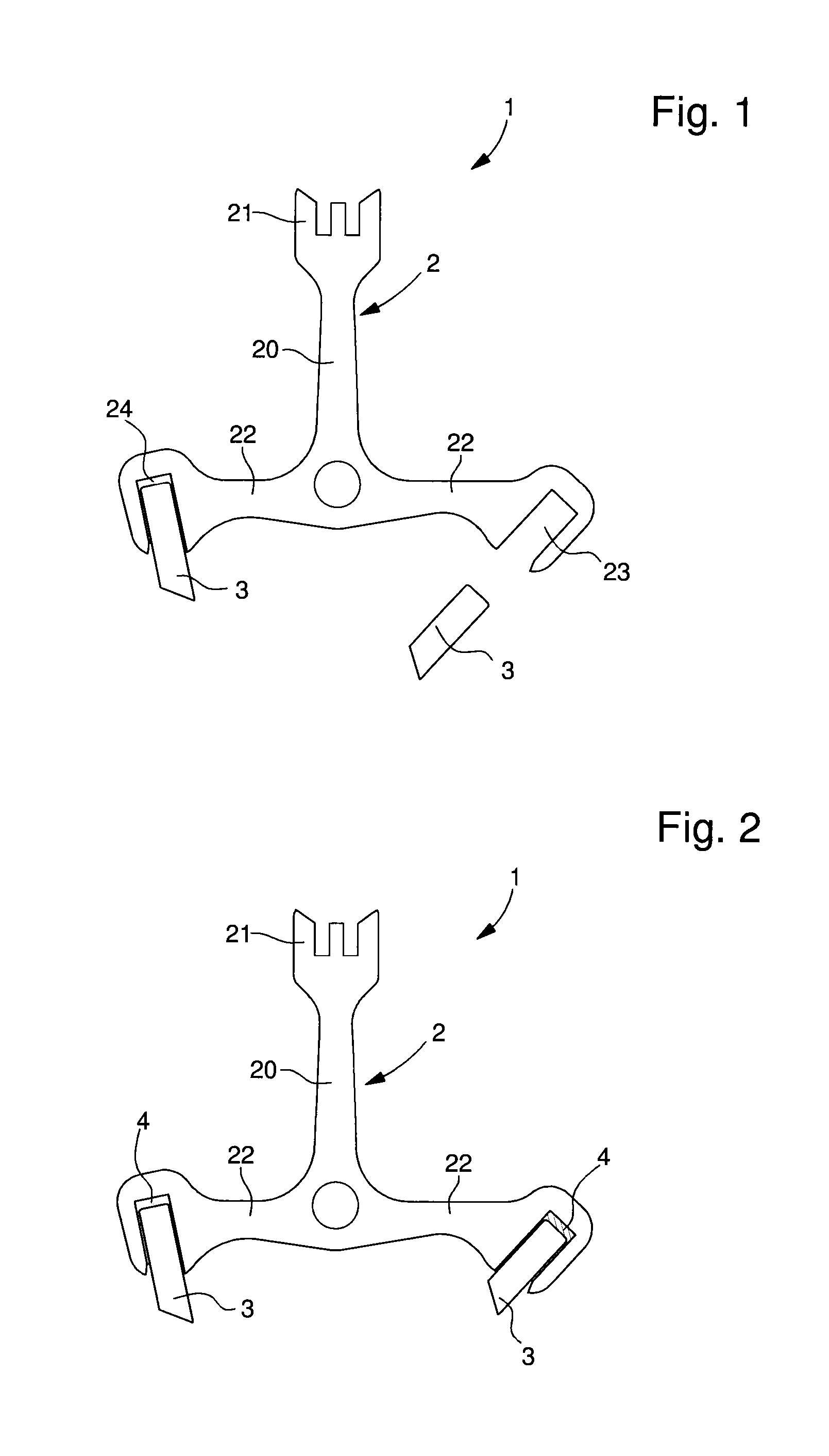
[0031]The assembly of the pallets 3 on the anchor 2 by means of the joint 4 precedes this adjustment step and can be achieved by different methods.

[0032]The property of amorphous materials that allows these to have a viscosity that decreases considerably in a given temperature range for each material while remaining amorphous is made use of to modify the position of the pallets 3 of the anchor 2.

[0033]The first step of th...

second embodiment

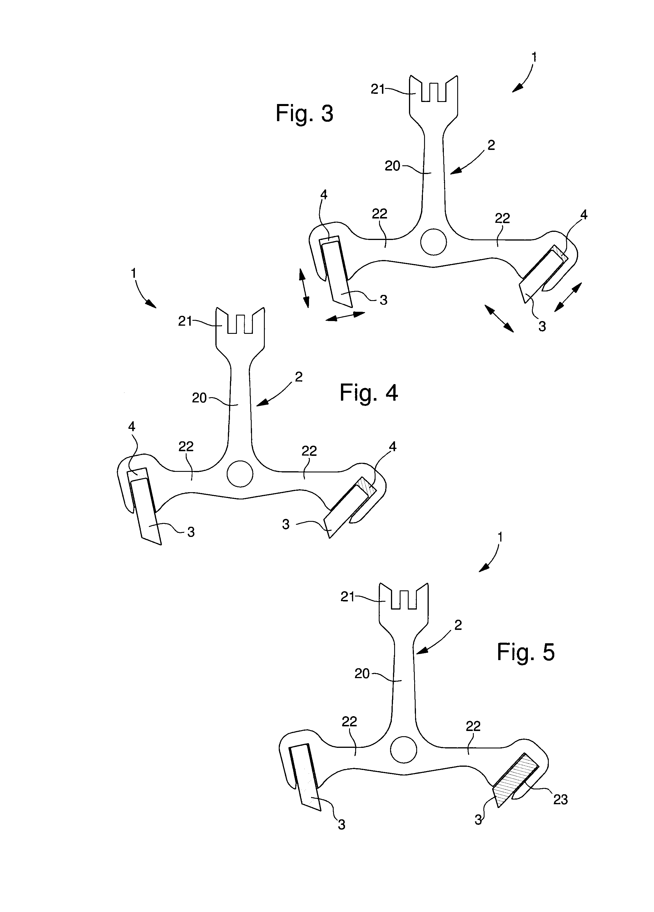
[0039]In the present invention shown in FIG. 5, the joint 4 and the anchor 2 form only one single piece. It is thus understood that the anchor 2 is made of the said first material and therefore of an amorphous metal. The anchor 2 thus acts as joint 4.

[0040]The anchor 2 can be made by hot or cold forming. The anchor 2 is thus formed at the same time as the pallets 3 are fixed to said anchor 2.

[0041]Once the anchor 2 has been formed, it is possible to adjust the position of the pallets 3 if these are not placed correctly.

[0042]The first step of this adjustment process therefore consists of providing said anchor 2, to which the pallets 3 are fixed.

[0043]The second step consists of increasing the temperature of at least one zone of the anchor 2. The increase in temperature must be conducted locally at the fixture zones between the first piece 2 and the second piece 3. In the case of an anchor 2, these zones are the zones of the seats of the arms 22 where the pallets 3 are inserted. Thes...


PUM

PropertyMeasurementUnit
Timeaaaaaaaaaa
Temperatureaaaaaaaaaa
Viscosityaaaaaaaaaa

Abstract

A process for adjusting a device including a first piece and at least one second piece, wherein the at least one second piece is fixed to the first piece by a joint made from a first material arranged between the first and second piece. The first material is an at least partially amorphous metal alloy. The process further includes: heating at least the joint to a heating temperature in a range of between a glass transition temperature and a crystallisation temperature of the first material; modifying a position of the at least one second piece until a desired determined position is obtained; cooling at least the joint so that it retains its at least partially amorphous state.

Description

[0001]The present invention relates to a process for adjusting a device. The device comprises a first piece and at least one second piece, wherein said at least one second piece is fixed to the first piece by means of a joint arranged between said first and second pieces.[0002]The technical field of the invention is the field of mechanics.TECHNOLOGICAL BACKGROUND[0003]There are numerous devices that after production require a step of adjustment in order to be perfectly compliant. This need for high precision exists in fields of microtechnology such as watchmaking, for example. In fact, the world of watchmaking works with dimensions from the millimetre to hundredth of a millimetre range. Examples of devices where precision is important include wheel trains or also the escapement. In actual fact, the escapement is formed from an anchor and an escape wheel cooperating with one another. The rotation of the latter is controlled by the anchor of the escapement system, the pulses of which ...

Claims


Application Information

Patent Timeline
IPC IPC(8): B23P6/00
CPCG04B13/022G04B15/14B23P6/00G04D3/00G04D3/0074B21D39/00G04B13/02
Inventor WINKLER, YVESBOURBAN, STEWESDUBACH, ALBAN
Owner THE SWATCH GRP RES & DEVELONMENT LTD
Why Eureka
Try Eureka