Electrode for electric storage device, electric storage device and manufacturing method of electrode for electric storage device
a manufacturing method and electric storage technology, applied in the direction of electrodes, coatings, material nanotechnology, etc., can solve the problems of carbon nanotubes hardly dispersed uniformly relative to the base material having projections and depressions, and the composition also has a problem in increasing the capacitance per unit area, etc., to improve the energy density to be stored, improve the capacitance and cell voltage, and improve the effect of energy density
- Summary
- Abstract
- Description
- Claims
- Application Information
AI Technical Summary
Benefits of technology
Problems solved by technology
Method used
Image

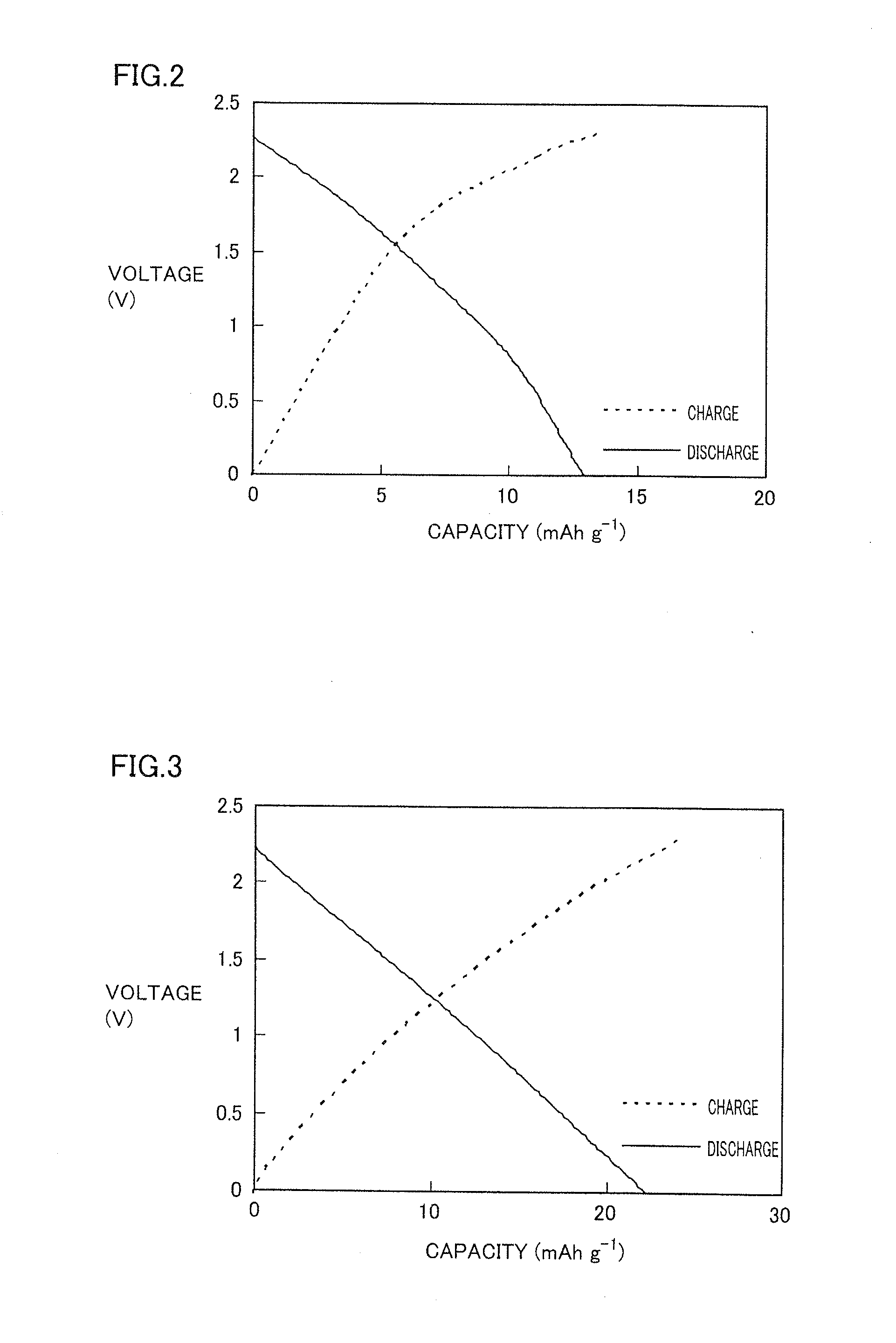
Examples
embodiment 1
Electrode for Electric Storage Device
[0056]In one embodiment of the present invention, an electrode for an electric storage device includes at least an active material selected from the group consisting of a carbon nanotube, activated carbon, hard carbon, graphite, graphene and a carbon nanohorn; an ionic liquid; and a three-dimensional network metal porous body.
(Active Material)
[0057]As the active material, at least one selected from the group consisting of a carbon nanotube, activated carbon, hard carbon, graphite, graphene and a carbon nanohorn can be used.
[0058]As the carbon nanotube, for example, a singlewall carbon nanotube (hereinafter, also referred to as a singlewall CNT) in which only one layer (graphene) of carbon is rolled into a tube, a doublewall carbon nanotube (hereinafter, also referred to as a doublewall CNT) in which a layer having a plurality of carbon layers laminated is rolled into a tube or a multiwall carbon nanotube (hereinafter, also referred to as a multiw...
embodiment 2
Electric Double Layer Capacitor
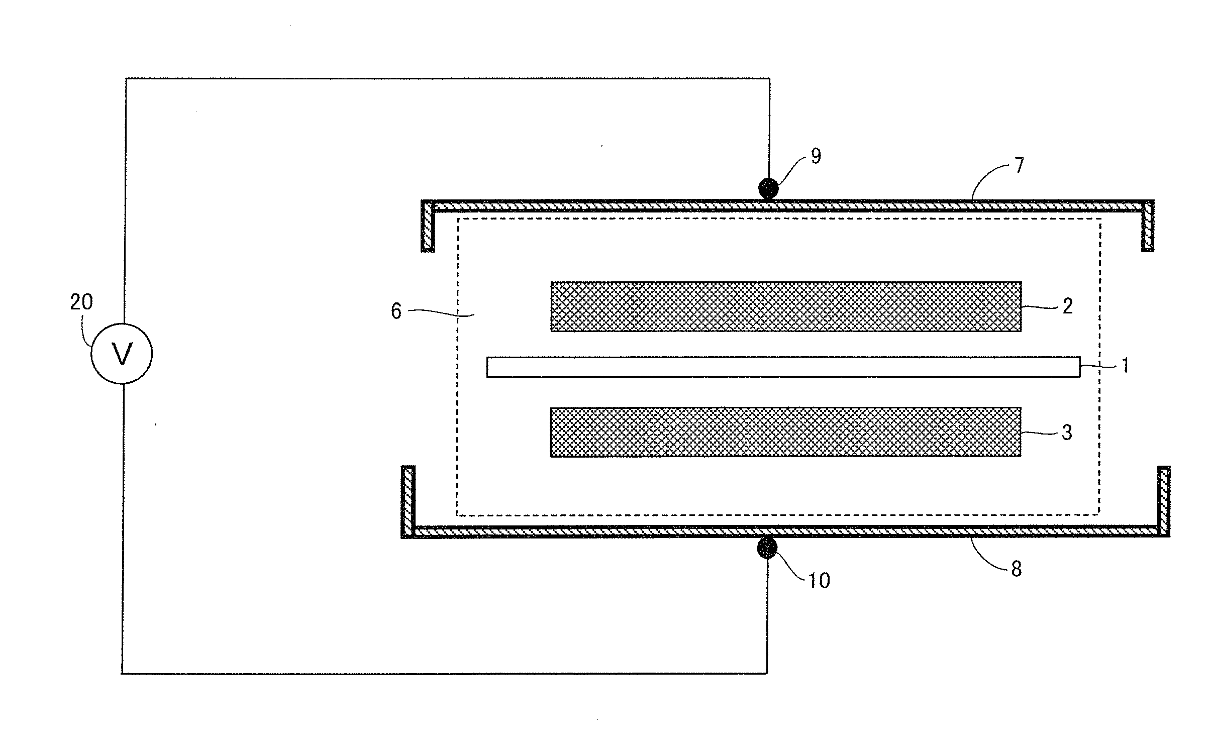
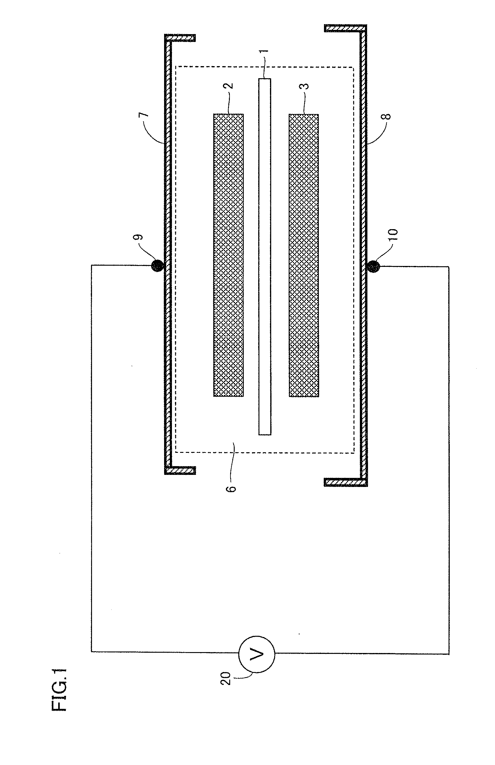
[0097]An electric double layer capacitor using the electrode for an electric storage device of the present invention will be described with reference to FIG. 1.
[0098]In the electric double layer capacitor using the electrode for an electric storage device of the present invention, a positive electrode 2 and a negative electrode 3 are located with a separator 1 sandwiched therebetween. Separator 1, positive electrode 2 and negative electrode 3 are hermetically sealed in a space filled with an electrolytic solution 6 between an upper cell case 7 and a lower cell case 8, respectively. Terminals 9 and 10 are disposed in upper cell case 7 and lower cell case 8. Terminals 9 and 10 are connected to a power source 20.
[0099]In the electric double layer capacitor, the electrode for an electric storage device of the present invention can be used for the positive electrode and the negative electrode.
[0100]For the electrolytic solution, an ionic liquid to be used f...
embodiment 3
[0103]A lithium-ion capacitor using the electrode for an electric storage device of the present invention will be described with reference to FIG. 10.
[0104]A structure of the lithium-ion capacitor using the electrode for an electric storage device of the present invention is basically similar to that of the electric double layer capacitor except that a lithium metal foil 16 is attached to the surface of negative electrode 3 opposed to positive electrode 2 by pressure.
[0105]In the lithium-ion capacitor, the electrode for an electric storage device of the present invention can be used for the positive electrode and the negative electrode. Further, the negative electrode is not particularly limited, and a conventional negative electrode using a metal foil can be used.
[0106]For the electrolytic solution, an ionic liquid containing a lithium salt to be used for the electrode for an electric storage device is used.
[0107]A lithium metal foil for lithium doping is attac...
PUM
| Property | Measurement | Unit |
|---|---|---|
| length | aaaaa | aaaaa |
| length | aaaaa | aaaaa |
| diameter | aaaaa | aaaaa |
Abstract
Description
Claims
Application Information
 - R&D
- Intellectual Property
- Life Sciences
- Materials
- Tech Scout
- Unparalleled Data Quality
- Higher Quality Content
- 60% Fewer Hallucinations
Browse by: Latest US Patents, China's latest patents, Technical Efficacy Thesaurus, Application Domain, Technology Topic, Popular Technical Reports.
© 2025 PatSnap. All rights reserved.Legal|Privacy policy|Modern Slavery Act Transparency Statement|Sitemap|About US| Contact US: help@patsnap.com