
Method for producing and electrical circuit and electrical circuit

Inactive Publication Date: 2013-06-13
ROBERT BOSCH GMBH
View PDF5 Cites 1 Cited by
  • Summary
  • Abstract
  • Description
  • Claims
  • Application Information

AI Technical Summary

Benefits of technology

The invention is a new electrical circuit and manufacturing process that allows for easier and more cost-effective manufacturing, increased heat dissipation, and more reliable and efficient heat dissipation. The circuit uses a prefabricated substrate with separate conductor layers for heat transfer and protection, and a thin insulating layer for high thermal conductivity. The manufacturing process protects the circuit components from heat and pressure during manufacture and assembly. The technical effects include simpler and more cost-effective manufacturing, improved heat dissipation, and better reliability and efficiency of the circuit.

Problems solved by technology

Higher temperatures, pressures or other manufacturing parameters can particularly be used, which would adversely affect other components like casting materials for embedding the circuit, semiconductor devices or thermally conductive pastes.

Method used


Image

  • Method for producing and electrical circuit and electrical circuit
  • Method for producing and electrical circuit and electrical circuit

Examples


Embodiment Construction

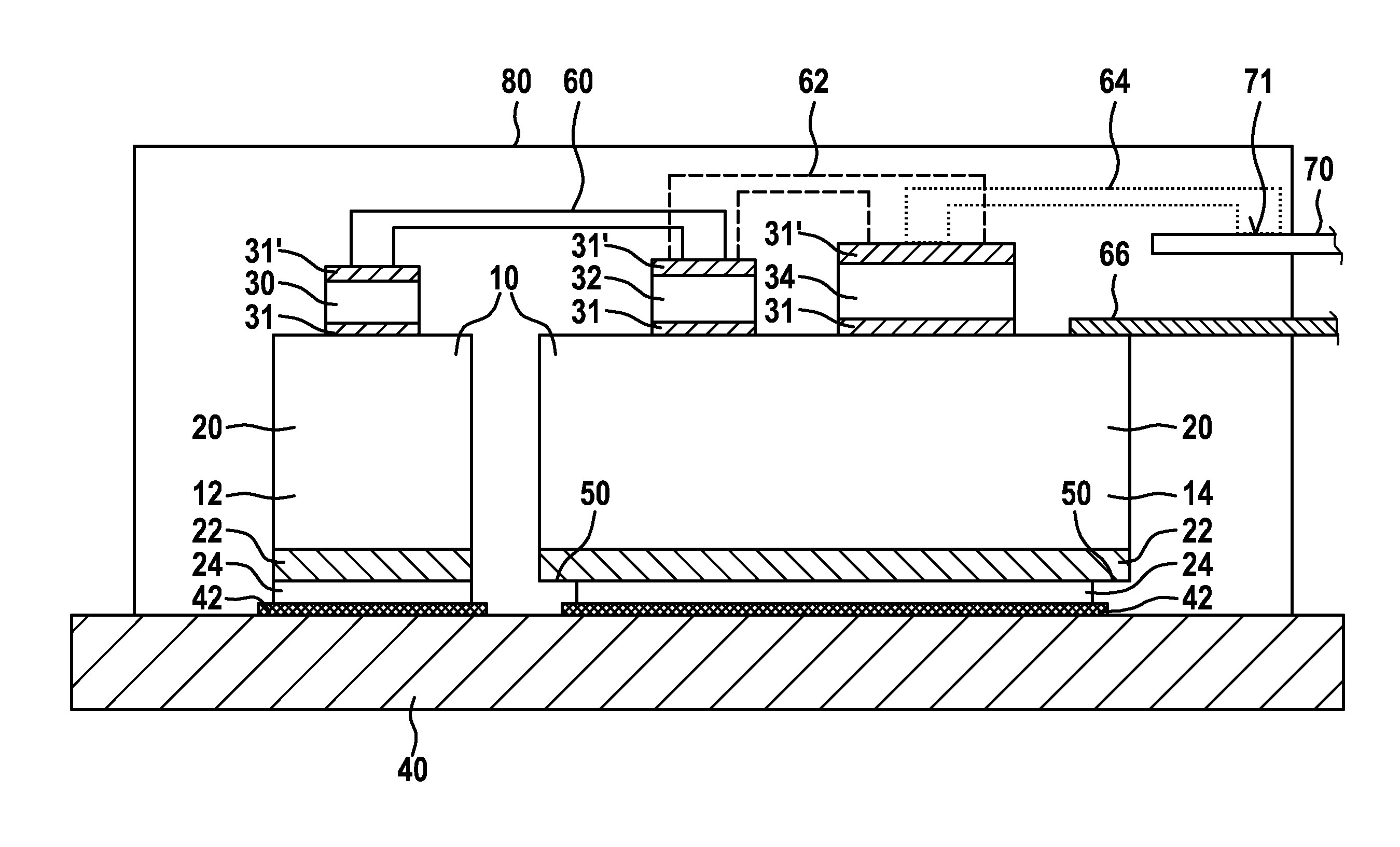
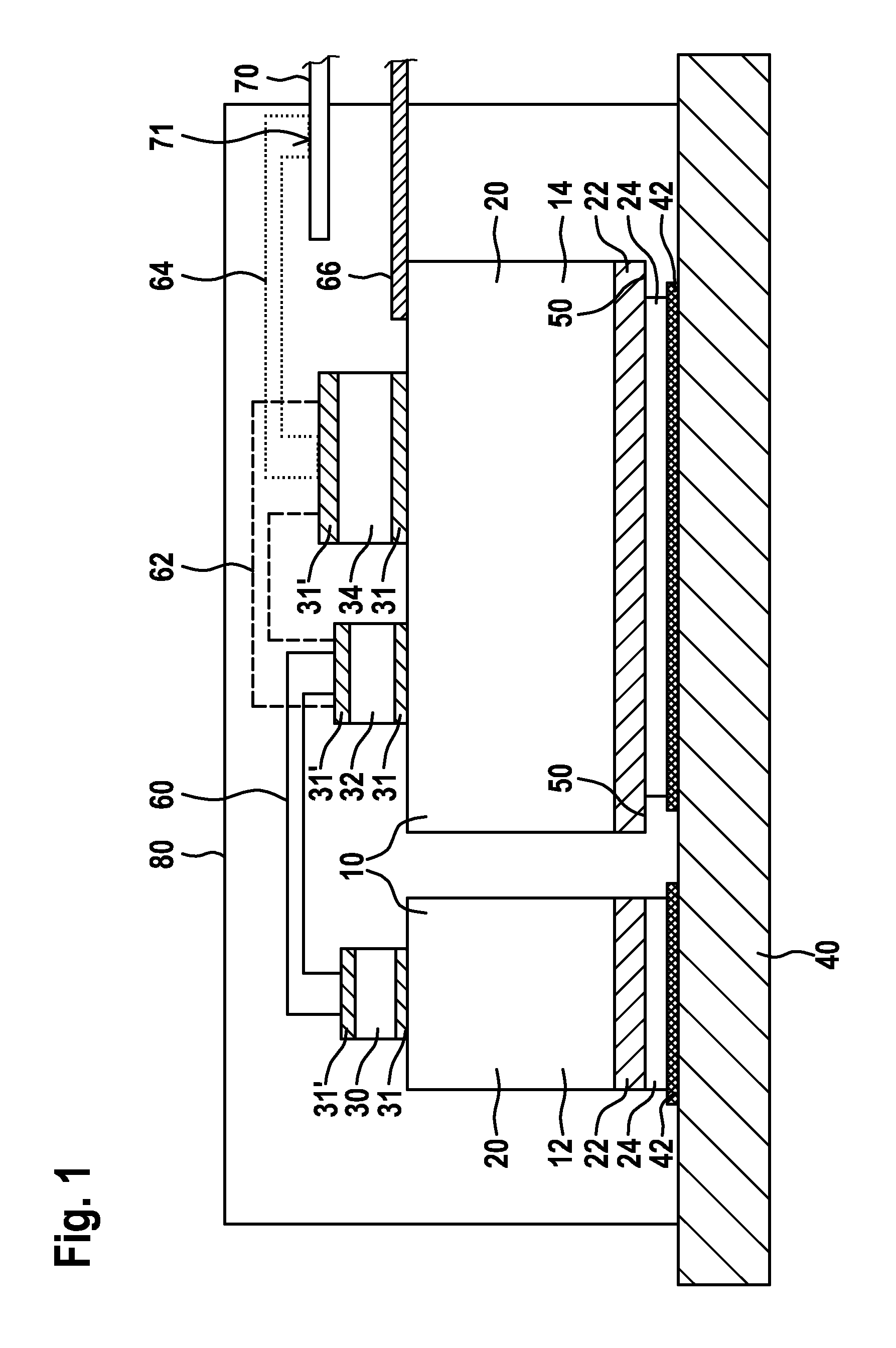
[0026]The exemplary embodiment of the inventive circuit depicted in FIG. 1 comprises a substrate 10, which is divided into two sections 12, 14. The substrate comprises a first conductor layer 20, a dielectric 22 in the shape of a layer and a second conductor layer 24. Components 30, 32, 34 are mounted on the first conductor layer 20 by means of soldered connections. The second conductor layer 24 of all of the sections is fastened via soldered connections 42 to a common heat sink in the form of a metal plate 40, a soldered connection 42 being provided for each section. An alternative, heat-transferring connection 42 would be an electrically insulating, heat-transferring connection in the form of a layer consisting of thermally conductive paste.

[0027]The second conductor layer 24 is undercut with respect to the dielectric, and therefore overhangs 50 are provided.

[0028]Each component 30-34 has an upper and a lower contact surface. The lower contact surface 31 is soldered directly onto ...


PUM

PropertyMeasurementUnit
Dielectric strengthaaaaaaaaaa

Abstract

The invention relates to a method for producing an electrical circuit. A prefabricated substrate is provided, said substrate having a first and a second conductor layer and having a dielectric between the first and the second conductor layers. According to the invention, the first conductor layer is multiple times thicker than the second conductor layer. At least one component to be cooled is mounted on the first conductor layer of the prefabricated substrate, forming a heat-transferring connection between the component and the first conductor layer. The invention further relates to an electrical circuit produced in said manner. According to the invention, the electrical circuit comprises a prefabricated substrate which is produced having a first and a second conductor layer and a dielectric located therebetween. According to the invention, the first conductor layer is multiple times thicker than the second conductor layer. At least one component to be cooled is mounted on the first conductor layer. According to the invention, there is a heat-transferring connection between the component and the first conductor layer.

Description

BACKGROUND OF THE INVENTION[0001]The use of heat sinks for the removal of dissipated heat of electrical or electronic components is known, said heat sinks being connected in a heat-conducting manner to the components via a printed circuit board or a substrate. The heat is initially transferred from the heat source, i.e. the components, to the printed circuit board to which said components are mounted. The heat is then transferred from the circuit board to the heat sink.[0002]So-called insulated metal substrates (IMS) comprise a thick metal plate, which is mounted to the heat sink, for improved heat dissipation, whereas a copper cladding, which is connected to the metal plate via a dielectric, provides conductor tracks for the electrical components to be mounted thereon. The copper cladding is of thin design (max. 300 μm) so that the conductor tracks can be formed by structuring said copper cladding, in particular by means of photolithography and subsequent etching. A disadvantage wh...

Claims


Application Information

Patent Timeline
IPC IPC(8): H05K3/30H05K1/02
CPCH01L21/4846Y10T29/49144H01L23/4334H01L25/072H05K7/20854H05K1/0204H05K3/303H01L2224/32225H01L2924/13055H01L23/3735Y10T29/4913H01L2924/1305H01L2924/13033H01L2924/1301H01L2924/00H01L23/373
Inventor GEINITZ, ECKART
Owner ROBERT BOSCH GMBH
Learn More