Underground Annular Blowout Preventer and Assembly Process Thereof

a technology of annular blowout and assembly process, which is applied in the direction of sealing/packing, other domestic objects, and borehole/well accessories. it can solve the problems of high-pressure oil and gas from the stratum entering the well accidentally, the well kicks and blowout accidents occur, and the pressure of the high-pressure oil and gas layer is difficult to predict. it is easy to prevent the blowout, the effect of high reliability

Active Publication Date: 2013-06-20
SOUTHWEST PETROLEUM UNIV
View PDF3 Cites 18 Cited by
  • Summary
  • Abstract
  • Description
  • Claims
  • Application Information

AI Technical Summary

Benefits of technology

[0013]Another advantage of the invention is to provide an underground annular blowout preventer that is simple in structure, innovative in design, and high in reliability.
[0014]Another advantage of the invention is to provide an underground annular blowout preventer that can be used together with an overflow and well kick pre-warning system and a check valve near the drill, wherein when the signal of underground well kick and blowout is received from the ground, the drill rod is lowered to increase drilling pressure to a specific level, so as to seal the well quickly and realize a communication between the inner side of the drill pipe and the annulus. The pipe column is then lifted to unseal the well.
[0015]Another advantage of the invention is to provide an underground annular blowout preventer is that the present invention can effectively prevent blowout accidents, and it has high feasibility, based on the following steps:
[0016](1) In the underground annular blowout preventer of the present invention, the torque transference between the upper and lower drill pipe is realized by the spline pair between the upper joint and the lower joint of the annular blowout preventer, so it can sustain a large torque. Each component of the blowout preventer is capable in handling a reasonable stress and is high in reliability.
[0017](2) The underground annular blowout preventer of the present invention can be mounted into a well at different depth over the demarcation point of drill pipe, and can allow multiple realization of sealing and unsealing of the drill without need of taking out the drill pipe to replace the blowout preventer. This helps to reduce cost of the equipment and the entire well drilling process due to the reusability.
[0018](3) Because of the first and second check valves, the underground annular blowout preventer of the present invention can prevent the high pressure fluid in the annulus from entering the drill pipe when the annular seal loses effectiveness due to other reasons.

Problems solved by technology

If a large amount of formation fluid enters the well, well kick, blowout, or even fire may result and cause a major accident.
However, it is very hard to predict the pressure of the high-pressure oil and gas layer, especially when drilling in the new blocks.
As a result, high pressure oil and gas from the stratum may accidentally enter the well during well drilling process.
In addition, well kick and blowout accidents occur in the following three states: during the drilling process, lifting and lowering the drill pipe, and emptying the well.
Because it is impossible to predict the pressure of a high pressure oil and gas layer during drilling process, the probability of well kick or blowout during this process is the highest.
The extra stratum fluid can cause additional pressure to the well head equipment and stratum, which makes well killing more difficult.
However, if the operator lacks of the experience or is negligent during work, the sign of well kick or blowout may not be discovered in time, and a major accident may occur.
After a well shut-in operation, the time required for well killing a well with heavy mud on the traditional well head blowout preventer is long, which results in more bottom fluid entering the well and increases the annular pressure difference, and thus it is more difficult to control blowout.
However, it has a complex structure and many components; therefore, it is complex to install, replace, and has an accordingly high cost.
After being used to prevent a blowout, the preventer can be recovered and reused from the original structure through the spring when there is no pressure difference, but if there is a pressure difference inside and outside the preventer, the preventer most likely cannot be recovered for reuse because elastic force of the spring is less than the pressure difference.
After being used multiple times, the spring can easily be broken; if the spring is broken when the blowout preventer is in use, the blowout preventer cannot be recovered and taken out, and thus the blocking caused thereby brings large inconveniences to the subsequent operations.
However, it has a complex structure and uses a shearing pin to seal; the pin is used to connect the upper and lower drilling tool and transfer the torque in the well drilling process, but the pin can be broken after undertaking long periods of variable shearing forces and variable torque because the drill pipe vibrates in drilling process.
Therefore, the reliability of the blowout preventer is not high since it is easy to cause an incorrect operation and due to an unexpected pin break a series of underground accidents can occur.
Moreover, when it is necessary to seal the high drilling pressure, the lower drill is required to cut the pin.
However, the lower drill components can only sustain a certain drilling pressure, which means that the process of cutting the pin can easily damage the lower drill components and cause an underground accident.
Even if all the operations before sealing the annulus are normal, if the annulus sealing is not complete, the high pressure stratum oil and gas inside the annulus can enter the drill pipe through the flow guiding hole, which makes the arrow-shaped check valve fail to seal the inner side of the drill and makes the well control more difficult.
Furthermore, after the pin is cut, well drilling has to be stopped and it is mandatory to take out the drill pipe and replace or maintain the all-in-one blowout preventer; that is, the blowout preventer can only be used once after being lowered to the well, which is unfavorable for reuse.
However, it has a complex structure and needs to be driven by a motor.
Some problems with this invention are that it is difficult to install the motor, and a high capacity power source is required in the narrow underground space.
There is doubt that whether the power provided by the motor can meet the minimum power requirements required by the sealing and unsealing processes (especially when the pressure difference is high).
Therefore, the safety and reliability of the patent are not high, and it is not very practical to be used in actual well drilling.

Method used


Image

  • Underground Annular Blowout Preventer and Assembly Process Thereof
  • Underground Annular Blowout Preventer and Assembly Process Thereof
  • Underground Annular Blowout Preventer and Assembly Process Thereof

Examples


embodiment 3

[0101]Embodiment 3 is similar to the Embodiments 1 and 2, as shown in FIG. 6, the difference is as follows:

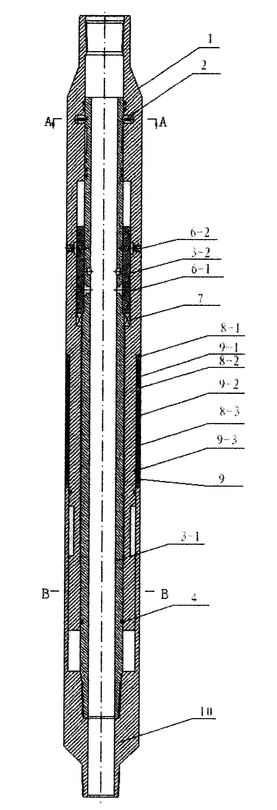
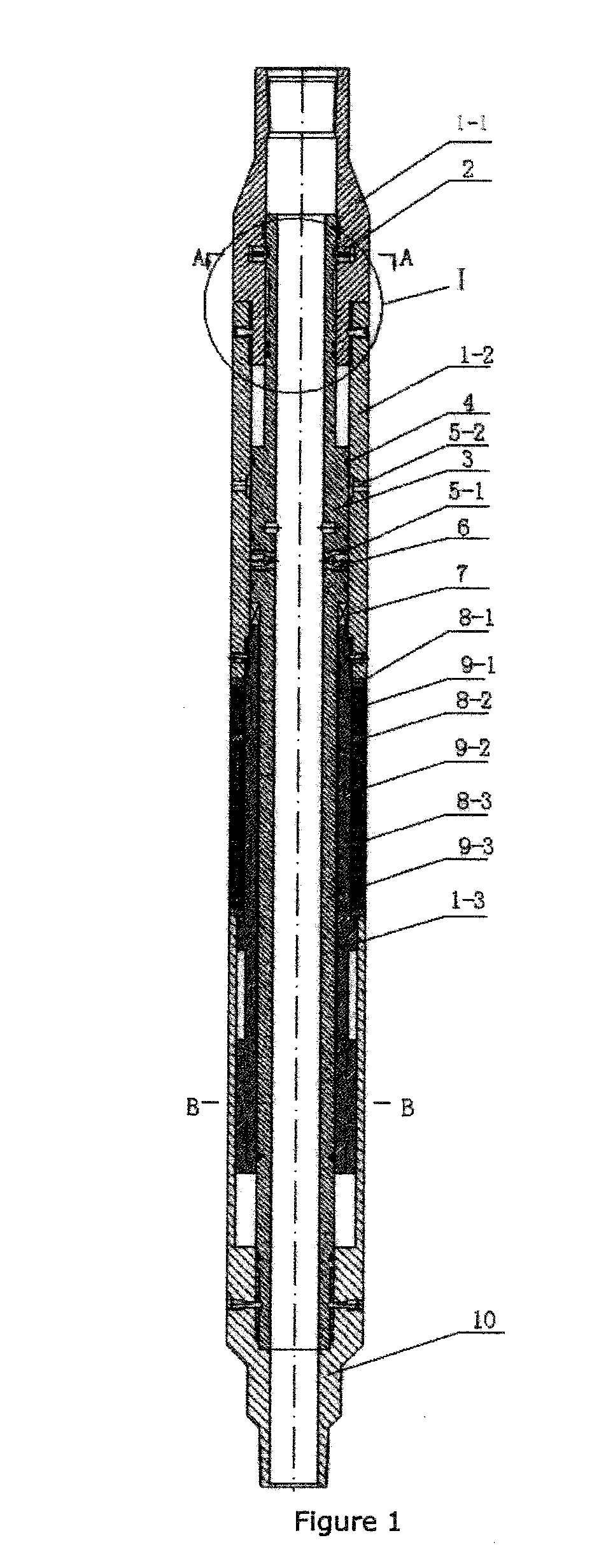
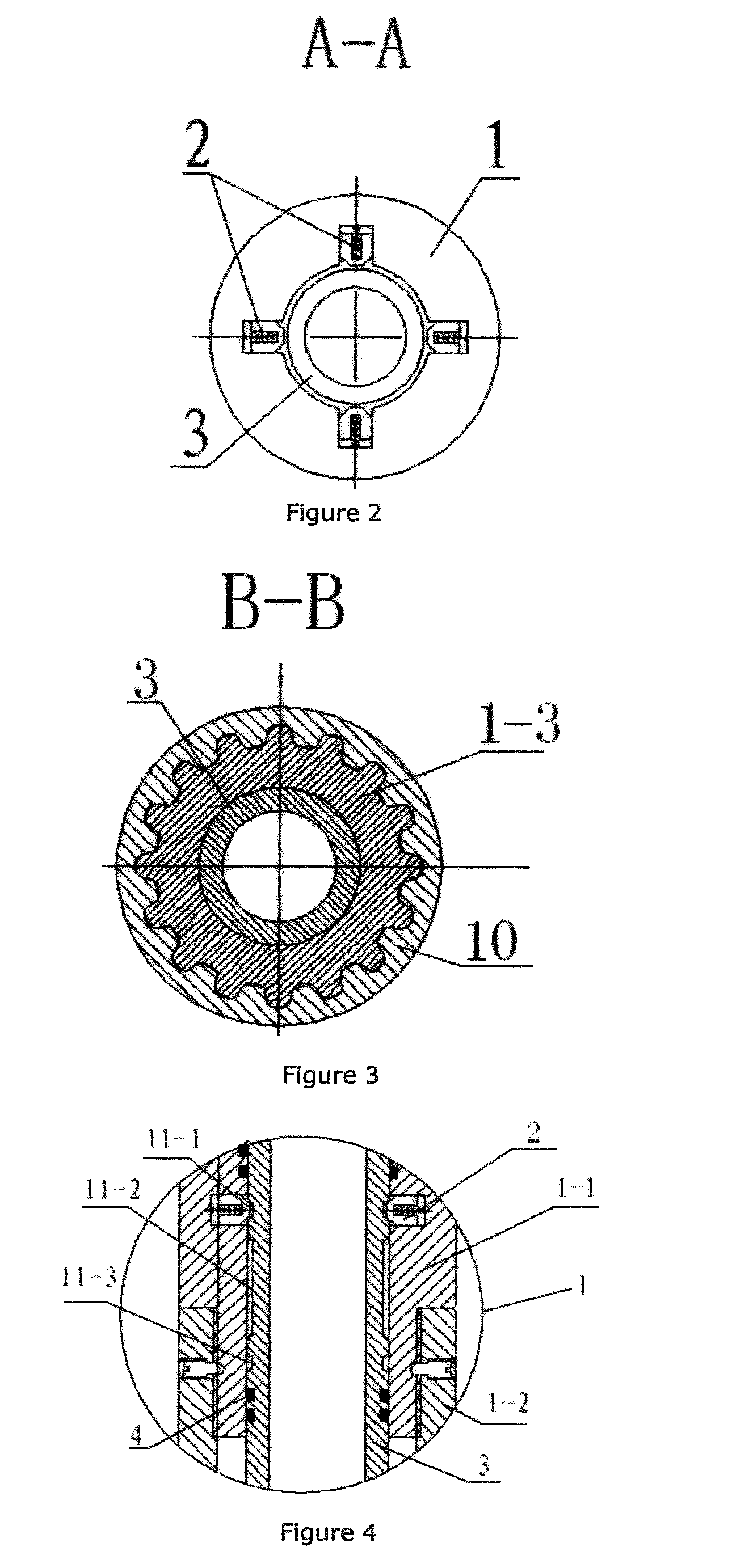
[0102]The upper connector 1-1 is integrated with the upper external sleeve 1-2 to form the upper joint component 1-a, and an inner sleeve 1-3 is fixedly connected inside the lower end of the upper joint component 1-a. The inner sleeve 1-3 is sleeved outside of the central barrel body 3-1, and lower end of the inner sleeve 1-3 is embedded between the lower joint 10 and the central barrel body 3-1. The outer wall of the lower end of the inner sleeve 1-3 is matched with the upper joint component 1-a through a spline, and the inner sleeve 1-3 can move freely relative to the lower joint 10 along the spline pair. A rubber barrel 9 is sleeved outside of the inner sleeve 1-3, and the upper end of which is embedded inside the upper joint component 1-a; therefore, both ends of the sleeve are in contact with the lower end face of the upper joint component 1-a and the upper end face of the...


PUM

PropertyMeasurementUnit
torqueaaaaaaaaaa
pressureaaaaaaaaaa
velocityaaaaaaaaaa

Abstract

An underground annular blowout preventer, which belongs to the technical field of underground blowout prevention, includes an upper joint and a lower joint are sleeved outside a central barrel. The lower end of the central barrel is fixedly connected with the lower joint. The lower end of the upper joint is sleeved on the inner side of the upper end of the lower joint. The upper joint is matched with the lower joint through a spline. The lower end of the upper joint can freely move relative to the lower joint along a spline pair. At least one rubber barrel is sleeved on the outer side of the upper joint. The rubber barrel can be extruded and expanded by the upper joint and the lower joint. The underground annular blowout preventer of the present invention can transmit large torque, has a simple structure, long service life, is convenient to use, and can be repeatedly used. The underground annular blowout preventer is used in coordination with a check valve of a near drill in the well drilling process, so that quick sealing of a well can be ensured, and well blowout accidents can be effectively prevented. A pipe column is lowered to seal the well and is lifted to open the well, and the inside of the drill rod is in communication with an annular space after the well is sealed, which facilitates replacement for heavy mud lubrication operations.

Description

NOTICE OF COPYRIGHT[0001]A portion of the disclosure of this patent document contains material which is subject to copyright protection. The copyright owner has no objection to any reproduction by anyone of the patent disclosure, as it appears in the United States Patent and Trademark Office patent files or records, but otherwise reserves all copyright rights whatsoever.BACKGROUND OF THE PRESENT INVENTION[0002]1. Field of Invention[0003]The present invention claims an underground annular blowout preventer, which belongs to the technical field of underground blowout prevention.[0004]2. Description of Related Arts[0005]In the task of oil exploration and oilfield development, well drilling is very important. Looking for and proving oil and gas bearing structures, obtaining industrial oil output, verifying oil and gas bearing areas and reserves of the proved oil and gas bearing structures, obtaining geological data and development data related to the oil field, and extracting the crude ...

Claims


Application Information

Patent Timeline
Patent Type & Authority Applications(United States)
IPC IPC(8): E21B33/06
CPCE21B33/10E21B33/06Y10T29/49412E21B21/10E21B34/10
Inventor LIU, QINGYOULI, WEI
Owner SOUTHWEST PETROLEUM UNIV
Why Eureka
Try Eureka