X-ray tube aperture having expansion joints

a technology of expansion joints and x-ray tubes, applied in the direction of x-ray tubes, nuclear engineering, nuclear elements, etc., can solve problems such as thermal expansion and contraction, and achieve the effects of reducing thermal stress, reducing failures, and increasing the overall operating life of x-ray tubes

Active Publication Date: 2013-06-20
VAREX IMAGING CORP
View PDF2 Cites 32 Cited by
  • Summary
  • Abstract
  • Description
  • Claims
  • Application Information

AI Technical Summary

Benefits of technology

[0015]Briefly summarized, embodiments of the present invention are directed to an electron shield for use in an x-ray tube and configured for interposition between an electron emitter and an anode configured to receive the emitted electrons. In example embodiments, the electron shield includes an electron collection surface, which is configured so that at least a portion of the electrons backscattered from the anode strike the collection surface instead of other areas of the x-ray tube. In addition, the electron shield is configured so as to reduce damage that might otherwise result from the high temperatures caused by the backscattered electrons striking the collection surface. This reduction in thermal stress reduces the incidence of failure in the electron shield and increases the overall operating life of the x-ray tube.
[0016]In one example embodiment the electron shield includes a body having an aperture formed through the center of the electron collection surface that defines a pathway for electrons to travel from the cathode to the anode surface. Electrons that rebound from the anode are collected at the electron collection surface and the resultant kinetic energy is released primarily in the form of heat, thereby causing the shield, particularly in the region of the collection surface adjacent to the aperture where more rebound electrons strike, to increase in temperature. During normal operation of the x-ray tube, this repeated heating of the electron shield results in thermal expansion and contraction. In an example embodiment, the shield is provided with one or more expansion joints positioned so as to minimize these “hoop” stresses by permitting the aperture to “expand” into the joints, thereby reducing damage to the shield that might otherwise occur.
[0017]In example embodiments, the expansion joints are provided in the form of one or more openings or gaps provided in electron shield so as to provide areas into which the aperture can expand when heated. These joints allow for elastic expansion and contraction in the aperture and / or the collection surface so as to reduce maximum mechanical stresses and reducing, for example, cracking and delamination at the collection surface. The electron shield is therefore better equipped able to withstand thermal stresses resulting in longer component life.
[0020]The body of the electron shield might be configured as a single integral piece of material. In other embodiments it is formed from multiple pieces and / or with different sections formed from different materials. For example, one example embodiment utilizes a bimetallic configuration. Here, the region of the electron shield that is impacted by relatively more backscattered electrons due to proximity to the anode target surface, such as a portion or the entire collection surface is comprised of a refractory material. Expansion joints such as slots are formed in the collection surface and extend from the aperture radially outward. The remainder of the body of the shield is composed of a metal having high thermal conductivity, such as copper. Use of the refractory metal, which is more heat resistant, increases the maximum input power capabilities by increasing the maximum operating temperature.
[0022]The cooling system can also include a plurality of extended surfaces, or cooling fins, that are affixed to the outer surface of the body of the shield structure and / or within the fluid passageway. The extended surfaces enhance the transfer of heat from the shield to coolant disposed within, for example, the x-ray tube housing in which the evacuated enclosure is disposed.
[0023]The inventive concepts provide a number of surprising advantages and benefits. For example, the lower stresses enabled by the expansion joints enable the use of organic-based heat transfer fluids as a shield coolant in lieu of water-based heat transfer coolants. In addition, the design allows for a small diameter aperture opening, resulting in the capture of a greater percentage of rebound electrons. In addition, lower cost materials can be used then what was previously required to maintain acceptable stress levels. The decreased thermal stresses that result from the design also increases the maximum heat loading capacity of both the electron shield and the tube. The design also increases the electron shield operating life for a given maximum power input. Moreover, it greatly reduces x-ray tube electrical arcs due to the reduction in aperture particles.

Problems solved by technology

During normal operation of the x-ray tube, this repeated heating of the electron shield results in thermal expansion and contraction.

Method used


Image

  • X-ray tube aperture having expansion joints
  • X-ray tube aperture having expansion joints
  • X-ray tube aperture having expansion joints

Examples


Embodiment Construction

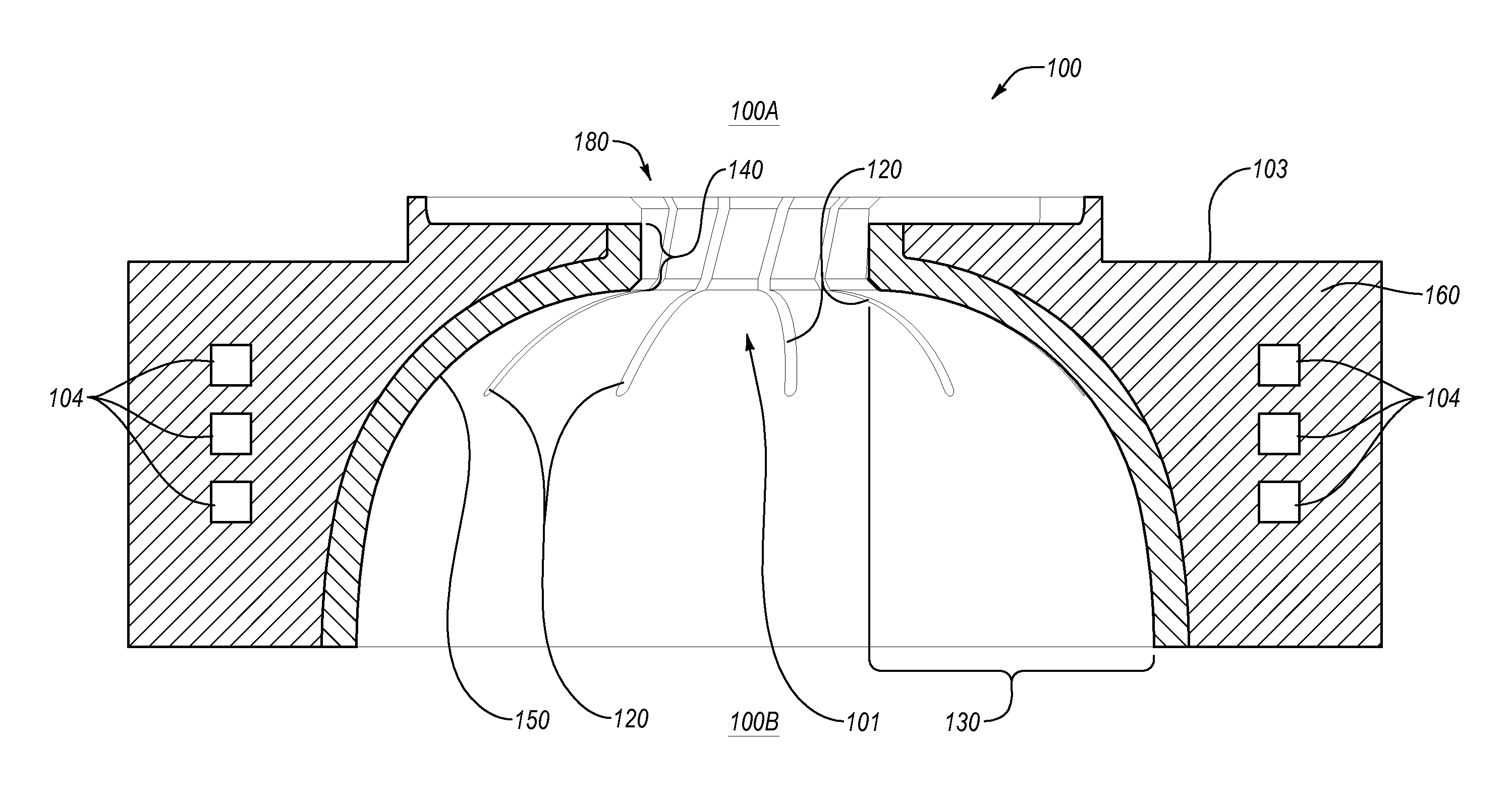
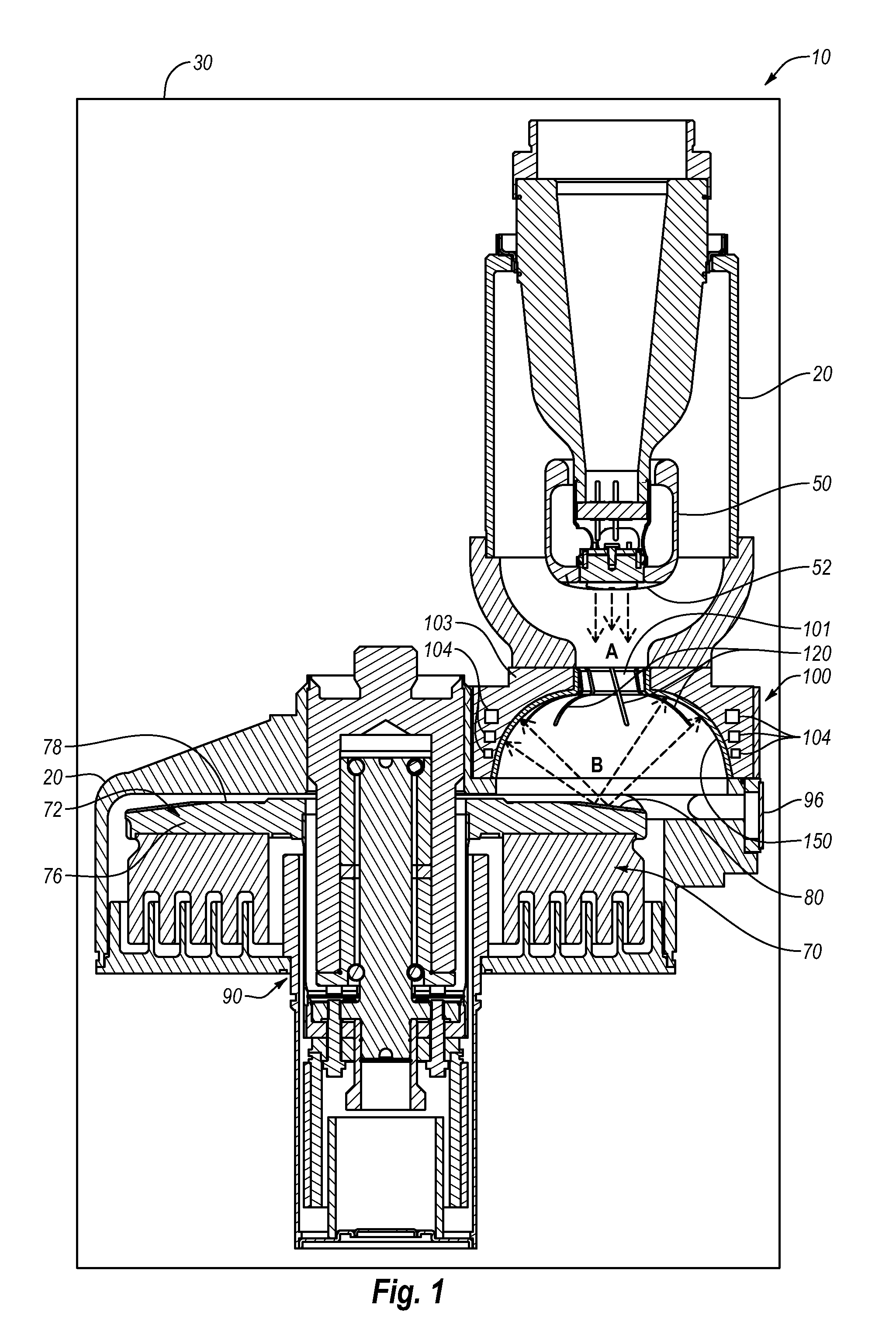
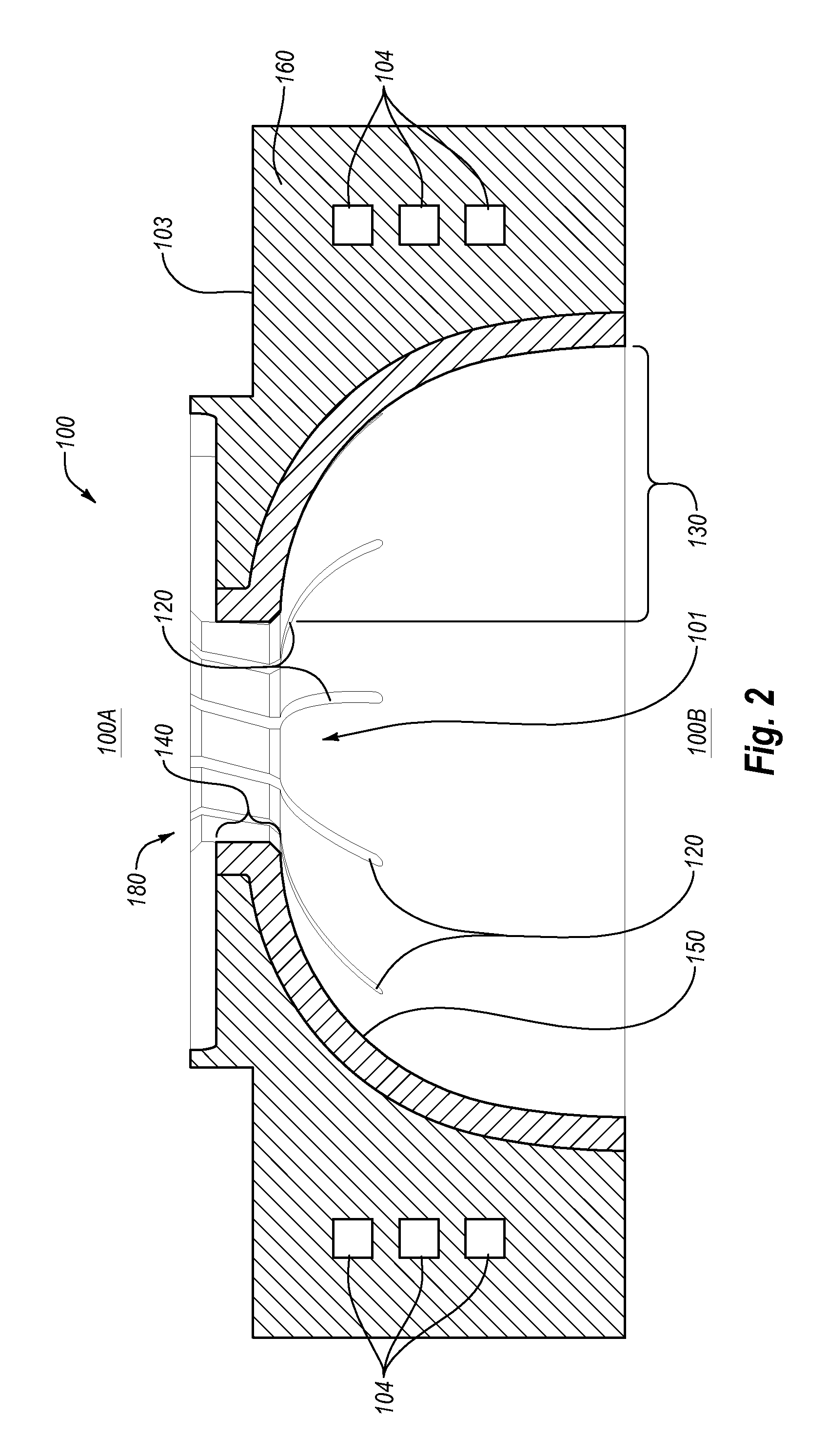
[0031]Reference will now be made to figures wherein like structures will be provided with like reference designations. It is understood that the drawings are diagrammatic and schematic representations of exemplary embodiments of the invention, and are not limiting of the present invention nor are they necessarily drawn to scale.

[0032]FIGS. 1-4 depict various features of example embodiments. In general, embodiments are generally directed to an electron shield for interposition between an electron emitter and an anode configured to receive the emitted electrons, such as in an x-ray tube. The primary function of the shield is to “collect” electrons backscattered from the anode. Advantageously, the electron shield is configured to withstand the elevated temperatures produced by backscattered electrons and incident on selected portions of the electron shield and resultant thermal stresses that occur. This in turn equates to a reduced incidence of failure in the electron shield and in the...


PUM


Abstract

An x-ray tube electron shield is disclosed for interposition between an electron emitter and an anode configured to receive the emitted electrons. The electron shield includes expansion joints to accommodate thermal expansion.

Description

BACKGROUND[0001]1. Technology Field[0002]Embodiments of the present invention generally relate to x-ray generating devices. More specifically, example embodiments relate to an electron shield configured to intercept and absorb backscattered electrons and having a construction that reduces heat-related damage.[0003]2. The Related Technology[0004]X-ray generating devices are extremely valuable tools that are used in a wide variety of applications, both industrial and medical. For example, such equipment is commonly employed in areas such as medical diagnostic examination, therapeutic radiology, semiconductor fabrication, and materials analysis.[0005]Regardless of the applications in which they are employed, most x-ray generating devices operate in a similar fashion. X-rays are produced in such devices when electrons are emitted, accelerated, and then impinged upon a material of a particular composition. This process typically takes place within an x-ray tube located in the x-ray gener...

Claims


Application Information

Patent Timeline
Patent Type & Authority Applications(United States)
IPC IPC(8): H01J35/18G21F3/00
CPCH01J35/16G21F3/00H01J2235/168
Inventor ANDREWS, GREGORY C.
Owner VAREX IMAGING CORP
Why Eureka
Try Eureka