Sheet metal turbine housing

a technology of metal turbines and housings, which is applied in the direction of machines/engines, stators, liquid fuel engines, etc., can solve the problems of reducing the driving performance of the turbine, affecting the efficiency of the turbine, and affecting the cooling efficiency of the catalyst, so as to improve the impact resistance, and reduce the effect of aging

Active Publication Date: 2013-06-20
MITSUBISHI HEAVY IND LTD
View PDF11 Cites 21 Cited by
  • Summary
  • Abstract
  • Description
  • Claims
  • Application Information

AI Technical Summary

Benefits of technology

[0023]The portion facing at least the outer circumference of the turbine wheel of the turbine has an increased sheet thickness, i.e., the portion on the outer side of the turbine wheel is made thicker, which allows for efficient prevention of damage to the housing portion caused by flying fractured pieces, because the fragments of the wheel will fly outward in the event of a burst following an excessively high-speed rotation of the turbine rotor.
[0024]In the present invention, the sheet metal scroll member of the scroll part should preferably have a double wall structure. With the sheet material of the scroll part having a double structure, the scroll part has better impact resistance, so that, in the event of a burst caused by an excessively high-speed rotation of the turbine rotor, fractured pieces are reliably prevented from flying off to the outside through the scroll member.
[0025]The doub

Problems solved by technology

As it is made by casting, the turbine housing is thick in various parts and has high heat capacity, because of which, when disposed upstream of an exhaust gas purification catalyst, the housing impedes the warming of the catalyst.
As the flange 03 on the bearing housing side, the flange 05 on the nozzle wall surface, and the coupling ring 08 are fabricated as separate components and welded

Method used


Image

  • Sheet metal turbine housing
  • Sheet metal turbine housing
  • Sheet metal turbine housing

Examples


first embodiment

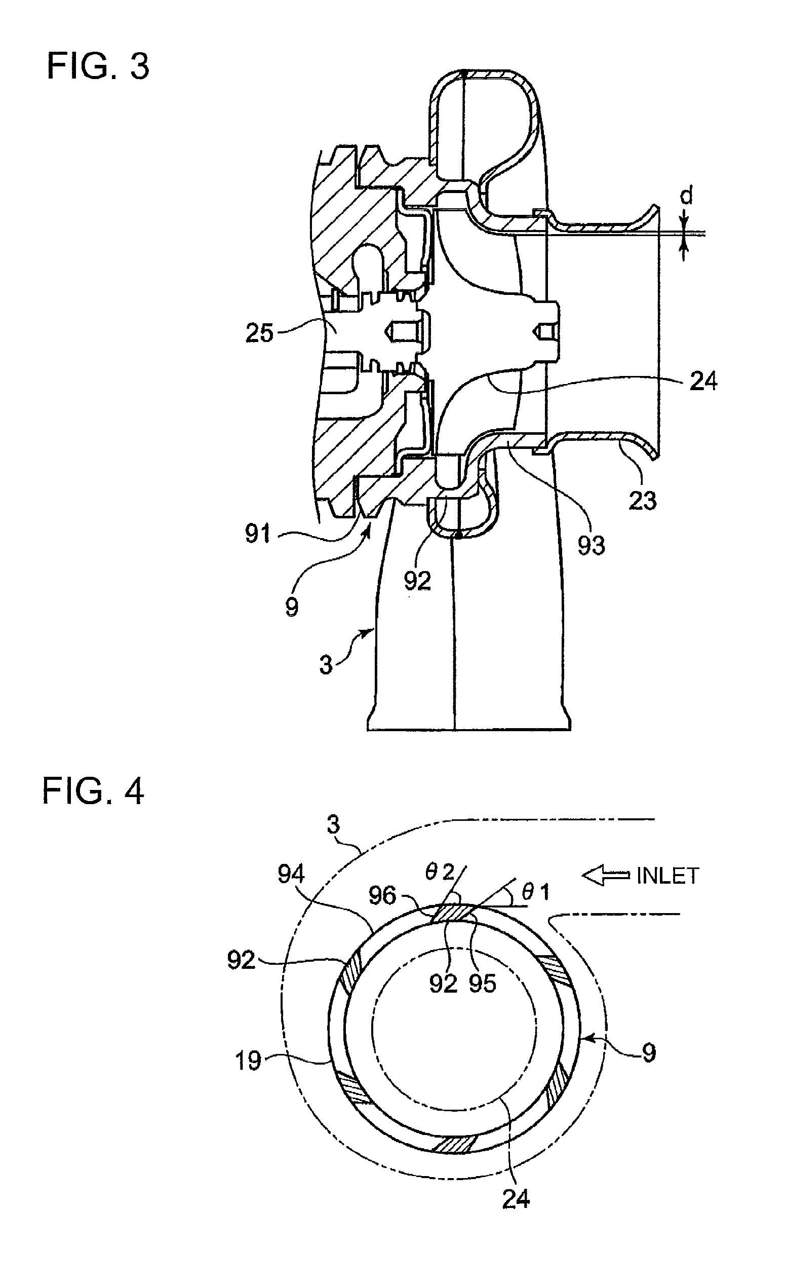
[0039]The turbine housing according to the first embodiment of the present invention will be described with reference to FIG. 1 to FIG. 4.

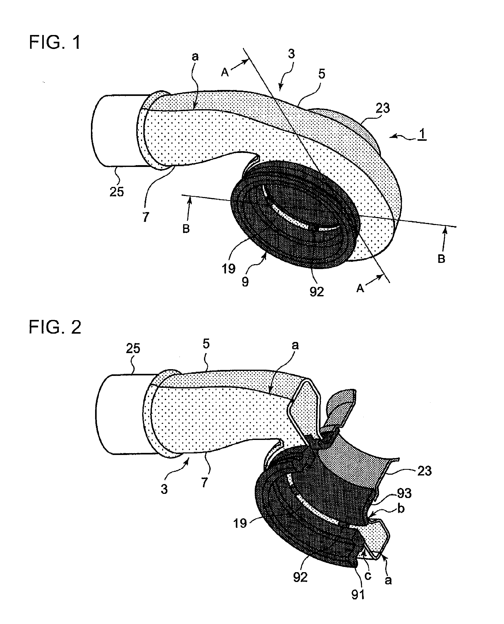
[0040]As shown in FIG. 1 and FIG. 2, the sheet metal turbine housing 1 is roughly made up of a scroll part 3, a center core part 9, and an outlet pipe part 23, the scroll part 3 being formed by a first scroll part 5 and a second scroll part 7 butted opposite each other and welded together. The turbine housing 1 is formed by joining these four parts by welding.

[0041]The scroll part 3 that forms a spiral gas passage is formed by butting two parts, the first scroll part 5 and the second scroll part 7, and joining them along the butted portion all around by penetration butt welding.

[0042]The sheet metal parts are welded together not by one-side fillet welding but by penetration butt welding wherein the ends of the sheet metal parts are butted against each other and welded (part a).

[0043]The first scroll part 5 and the second scroll part 7 may be thin ...

second embodiment

[0065]Next, the second embodiment will be described with reference to FIG. 5.

[0066]Elements that are the same as those of the first embodiment are given the same reference numerals in FIG. 5. At the volute center of the scroll part 31 is the center core part 33, which is generally cylindrical as a whole, and includes a bearing receiving portion 35 in which a bearing for supporting the rotating shaft of the turbine wheel 24 is fitted, a housing portion 37 that surrounds the outer circumference of the turbine wheel 24 to form a gas discharge port, and a plurality of circumferentially spaced supports 92 bridging a gap between the bearing receiving portion 35 and the housing portion 37, these all being formed in one piece.

[0067]This center core part 33 is made of the same material and produced by the same method as that of the first embodiment described in the foregoing.

[0068]Although the configuration of the second embodiment shown in FIG. 5 does not include the outlet pipe part 23 of ...

third embodiment

[0078]Next, the third embodiment will be described with reference to FIG. 8. The third embodiment is characterized in that the sheet metal scroll member of the scroll part 41 has a double wall structure, unlike the structure in the second embodiment

[0079]As shown in FIG. 8, the scroll part 41 is formed by an inner wall 43 and an outer wall 45, the inner wall 43 serving a function of withstanding thermal stress from the internal gas, and the outer wall 45 serving a function of preventing a gas leak.

[0080]An air layer K is present between the inner wall 43 and the outer wall 45 to form an insulation layer.

[0081]With such a double wall structure, the part C can absorb more energy through fracture, and the amount of energy absorbed by the part C is about 25% in the third embodiment, as compared to the scroll part 31 having a single wall structure in the second embodiment. As a result, the thick portion X need only have a sheet thickness and a length to be able to absorb about 60% or mor...


PUM


Abstract

The turbine housing 1 is formed by sheet metal scroll members 5 and 7 butted opposite each other and welded together. A center core part 9 arranged in a central part of the scroll part 3 is integrally formed in one piece from a steel pipe member such as to include a housing portion 93 surrounding a turbine wheel 24, a bearing receiving portion 91 axially supporting the turbine wheel 24, and a plurality of circumferentially spaced supports 92 bridging a gap between the housing portion 93 and the bearing receiving portion 91.

Description

TECHNICAL FIELD[0001]The present invention relates to a sheet metal turbine housing employed in a turbocharger that sends compressed air to the engine by using the energy of exhaust gas from the engine, and more particularly to the surrounding structure of a center core part of the turbine housing.BACKGROUND ART[0002]A conventional turbine housing 001 includes, as shown in FIG. 9, a scroll part 002, a core part 003 surrounding the outer circumference of a turbine wheel 004, and an outlet part 005 leading to an exhaust gas flow passage, these being formed integrally by casting. As it is made by casting, the turbine housing is thick in various parts and has high heat capacity, because of which, when disposed upstream of an exhaust gas purification catalyst, the housing impedes the warming of the catalyst. In view of more stringent exhaust gas regulations in recent years, it is important to reduce the heat capacity of the housing by making it from sheet metal so that it is thinner and ...

Claims


Application Information

Patent Timeline
IPC IPC(8): F01D25/24
CPCF01D25/24F01D9/026Y02T50/671F05D2230/54F05D2230/232F02B37/02F02B39/00F05D2220/40Y02T50/60
Inventor NAGAE, SATOMIWATANABE, DAIGOEBISU, MOTOKIKYOYA, MICHIOKIKUCHI, TORU
Owner MITSUBISHI HEAVY IND LTD
Why Eureka
Try Eureka