
Structure and method for attaching tactile sensor to curved surface

a technology of tactile sensors and structures, applied in the direction of force/torque/work measurement apparatus, manufacturing tools, instruments, etc., can solve the problems of not being applied to an organ, tactile sensors without flexibility, and low sensitivity, and achieve the effect of being easily attached to the curved surfa

Inactive Publication Date: 2013-07-04
KOREA RES INST OF STANDARDS & SCI
View PDF6 Cites 31 Cited by
  • Summary
  • Abstract
  • Description
  • Claims
  • Application Information

AI Technical Summary

Benefits of technology

The present invention aims to provide a structure and method for easily attaching a curved surface type tactile sensor to a concave or convex curved surface. This allows for mass production of the tactile sensors while maintaining their functionality. The technical effect of the invention is to provide a more efficient and flexible attachment mechanism for curved surface sensors.

Problems solved by technology

The bio-mimetic tactile sensor is for a force / torque sensor of 6 degrees of freedom which is already used in the wrist of an industrial robot and the gripper of a robot and is configured to detect contact pressure and instant sliding, but is problematic in that it has a low sensitivity owing to a relatively bulky detection unit.
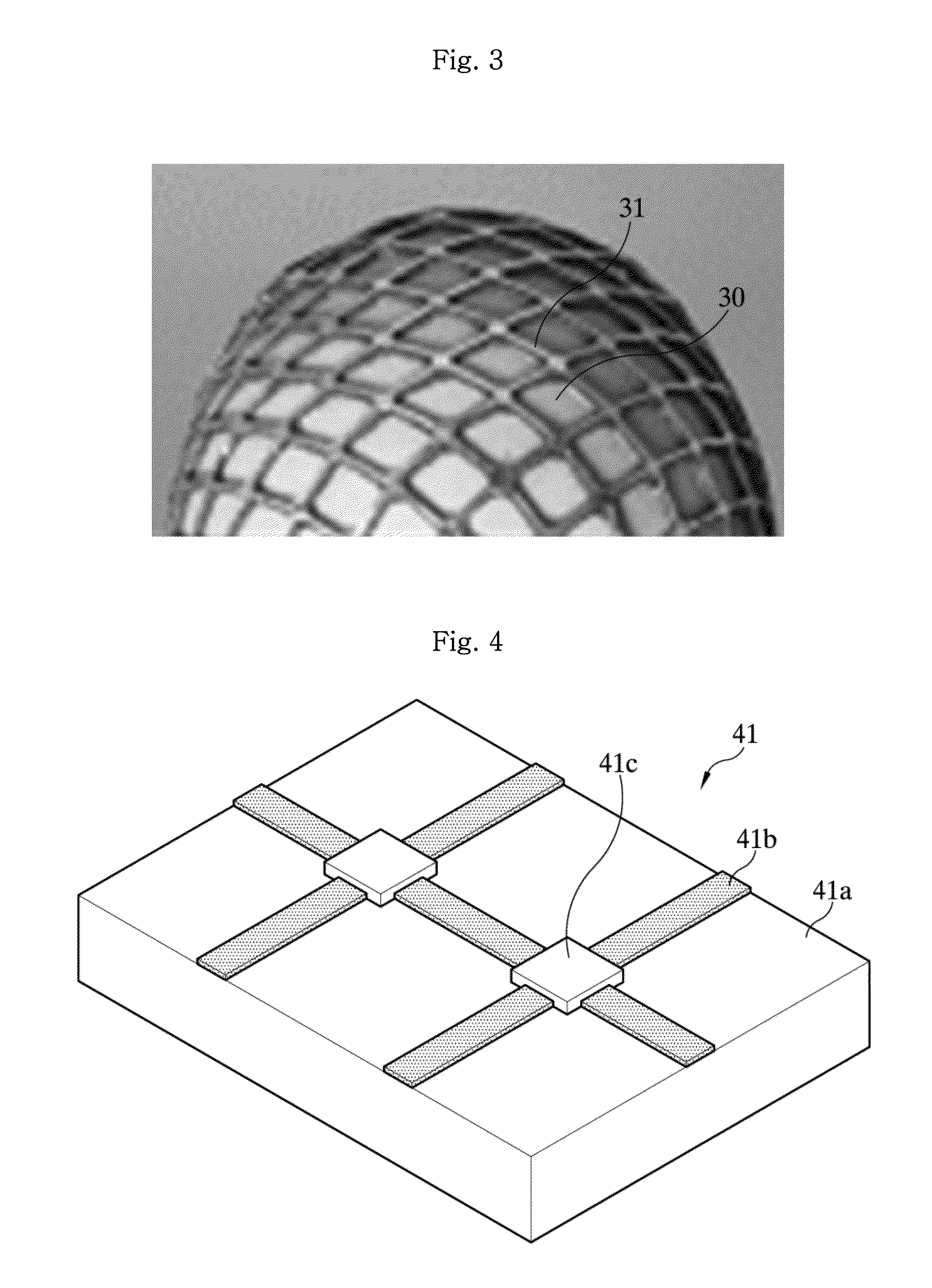
However, this technology is problematic in that the tactile sensor does not have flexibility because a sensor is formed using a silicon wafer.
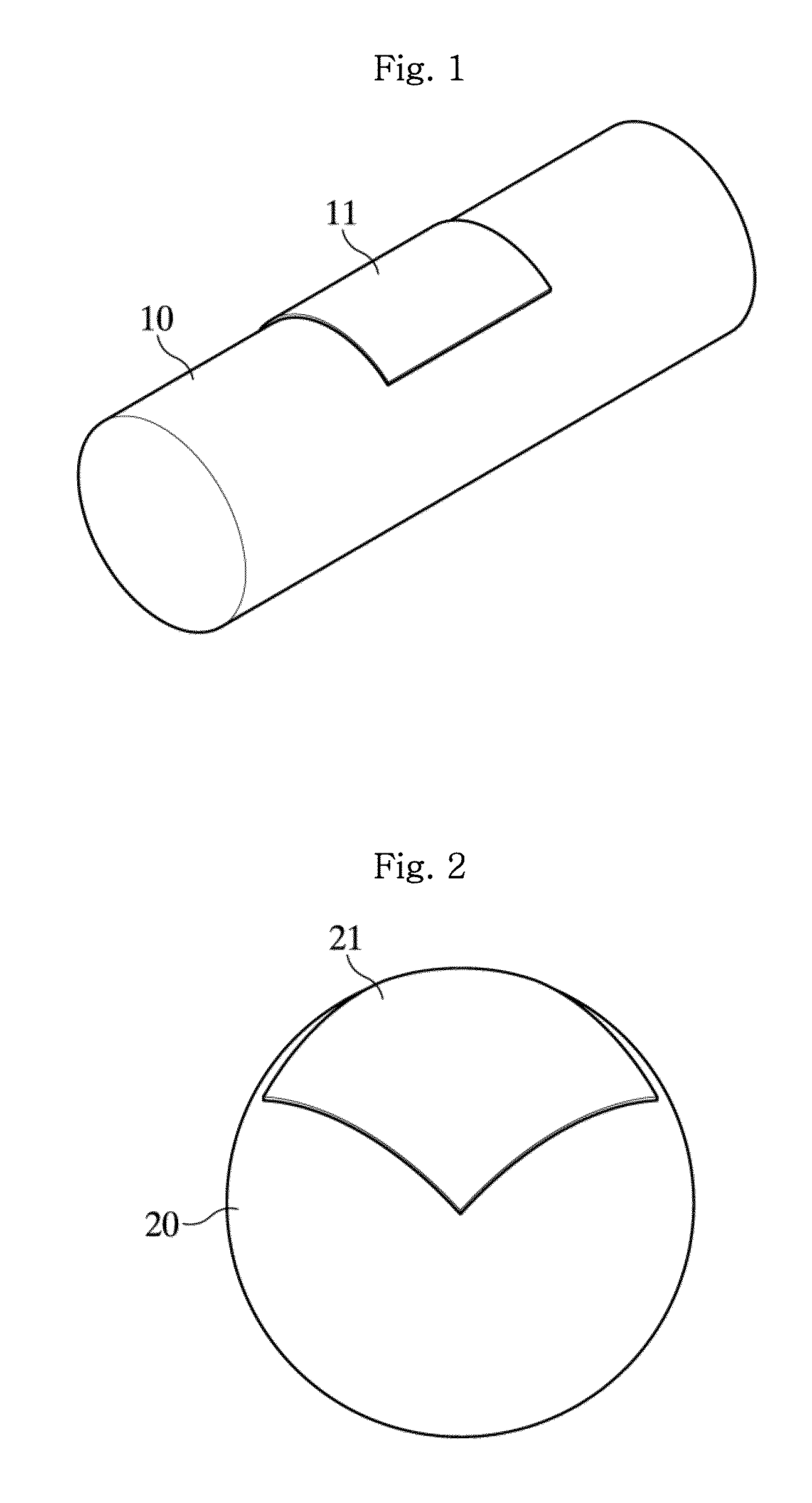
Accordingly, the tactile sensor 31 may be applied to a globular shape having a large cylinder or a large curvature, but has a problem in that it may not be applied to an organ, such as a finger of a human type robot, or a very small globular shape because it lacks soft like a human skin.
Furthermore, there are problems in that automation is difficult and an individual manual work is necessary because the tactile sensor 31 must be attached one by one.
The tactile sensor 41, however, is problematic in that a crack is generated in the metal line 41b if peeling is generated between the metal lines 41b and the substrate 41a or if slight deformation occurs and the tactile sensor 41 is worn by a continuous contact.

Method used


Image

  • Structure and method for attaching tactile sensor to curved surface
  • Structure and method for attaching tactile sensor to curved surface
  • Structure and method for attaching tactile sensor to curved surface

Examples


first embodiment

Manufacturing Method of First Embodiment

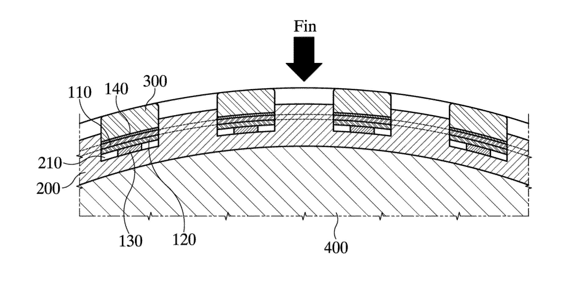
[0098]FIG. 14 is a flowchart illustrating a method of attaching tactile sensors to a curved surface according to a first embodiment of the present invention. The method of attaching tactile sensors to a curved surface according to the first embodiment of the present invention is described in detail below with reference to FIGS. 5 to 8 and 14.

[0099]The method of attaching tactile sensors to a curved surface according to the first embodiment of the present invention chiefly includes a temperature sensor unit insertion step (S110), a tactile sensor unit insertion step, a sealing step (S140), a locking unit coupling step (S150), and a support unit insertion step (S160).

[0100]First, in the temperature sensor unit insertion step (S110), the temperature sensor units 140 are inserted into the respective sensor insertion grooves 210 of the sensor fixing unit 200 in a row.

[0101]Next, the tactile sensor unit insertion step includes a second sensor layer ...

second embodiment

Manufacturing Method of Second Embodiment

[0108]FIG. 15 is a flowchart illustrating a method of attaching tactile sensors to a curved surface according to a second embodiment of the present invention. The method of attaching tactile sensors to a curved surface according to the second embodiment of the present invention is described in detail below with reference to FIGS. 9 to 11 and 15.

[0109]The method of attaching tactile sensors to a curved surface according to the second embodiment of the present invention chiefly includes a tactile sensor unit insertion step, a temperature sensor unit insertion step (S230), a sealing step (S240), a locking unit coupling step (S250), and a support unit insertion step (S260).

[0110]The tactile sensor unit insertion step includes a second sensor layer insertion step (S210) and a first sensor layer insertion step (S220). First, in the second sensor layer insertion step (S210), the second sensor layer 120 is inserted into the sensor insertion groove 21...


PUM

PropertyMeasurementUnit
contact resistance methodaaaaaaaaaa
piezoelectric materialaaaaaaaaaa
pressureaaaaaaaaaa

Abstract

The present invention relates to a structure for attaching tactile sensors to a curved surface, comprising a sensor fixing unit configured to have at least part of one surface curved and to have a plurality of sensor insertion grooves, crossing each other, formed in the one surface in a matrix form; tactile sensor units formed in a matrix form, inserted into the respective sensor insertion grooves, and configured to detect external force; sealing units configured to seal the respective sensor insertion grooves; and a support unit configured to come in contact with one face of the sealing units or the sensor fixing units and to support the sensor fixing units. Accordingly, the tactile sensors can be easily attached to a curved surface, and mass production is possible.

Description

CROSS-REFERENCE TO RELATED APPLICATION[0001]Priority to Korean patent application number 10-2011-0144614 filed on Dec. 28, 2011, the entire disclosure of which is incorporated by reference herein, is claimed.BACKGROUND OF THE INVENTION[0002]1. Field of the Invention[0003]The present invention relates to a structure and method for attaching tactile sensors to a curved surface and, more particularly, to a structure and method for attaching a curved surface type tactile sensor, wherein the tactile sensor is inserted into a sensor fixing unit having sensor insertion grooves formed in a concave or convex curved surface, thereby enabling the tactile sensor to be easily attached to the curved surface and enabling mass production.[0004]2. Background of the Related Art[0005]A tactile function for obtaining pieces of information (i.e., the intensity of contact force, vibration, surface roughness, and a temperature change of thermal conductivity) about surrounding environments through a contac...

Claims


Application Information

Patent Timeline
Patent Type & Authority Applications(United States)
IPC IPC(8): H05K7/00B23P17/00
CPCA61B2562/0247A61B2562/046Y10T29/4998G01L1/146G01L1/205A61B2562/164B25J19/02G01L1/00G01L5/00
Inventor KIM, JONG HOKIM, MIN SEOKPARK, YON-KYUKANG, DAE IMKIM, DONG-KI
Owner KOREA RES INST OF STANDARDS & SCI
Learn More