Method for efficiently recovering platinum group elements from copper-iron scrap

a platinum group element and scrap technology, applied in the field of efficiently recovering platinum group elements from copper iron scrap, can solve the problems of difficult selection of an efficient process for platinum, large amount of acid, and difficulty in actual practice for recovering platinum from molten iron phase, and achieve efficient recovery of platinum group elements, high distribution ratio, and efficient concentrating of platinum group elements

Inactive Publication Date: 2013-07-18
NIPPON STEEL CORP
View PDF1 Cites 5 Cited by
  • Summary
  • Abstract
  • Description
  • Claims
  • Application Information

AI Technical Summary

Benefits of technology

[0016]The object of the present invention is to provide a means for efficiently recovering platinum group elements from copper-iron scrap containing platinum group elements typified by platinum by efficiently concentrating platinum group elements in a molten copper phase which is obtained from the copper-iron scrap.
[0017]Upon investigation of the distribution of rare metals in a copper phase and an iron phase and the interaction of

Problems solved by technology

Namely, Non-Patent Document 1 suggests that with an iron (Fe)-copper (Cu)-carbon (C) system, it is difficult to select an efficient process in which platinum is concentrated in one of the phases and is recovered from the concentrated p

Method used


Image

  • Method for efficiently recovering platinum group elements from copper-iron scrap
  • Method for efficiently recovering platinum group elements from copper-iron scrap

Examples


example 1

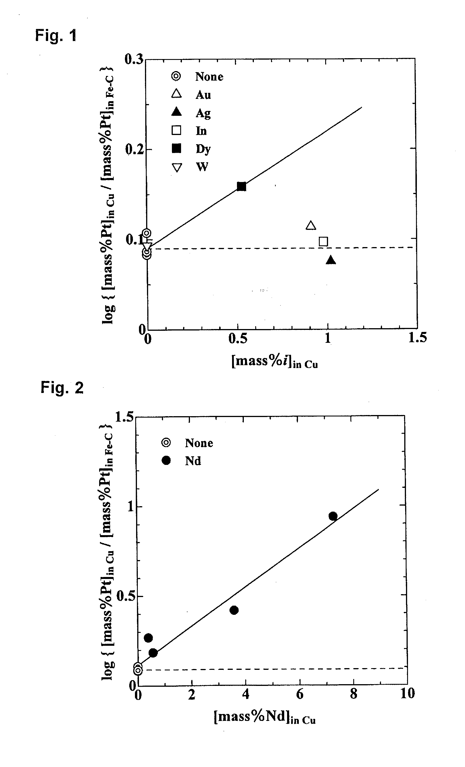
[0084]5 grams of C-saturated Fe, 5 grams of Cu, and 0.05 grams of Pt were placed into a graphite crucible. In each experiment, under conditions in which from 0.7 to 1 gram of Au, Ag, In, Dy, or W was or was not added, the mixture was melted at 1823 K using an electric furnace in an atmosphere containing 100 ml / min of Ar (converted to standard conditions) and held for 2 hours. The sample was then removed from the furnace and cooled by blowing Ar gas.

[0085]Table 3 shows the concentration of added element i in the copper phase [mass % i]in Cu and the concentration of added element i in the iron phase [mass % i]in Fe-C in the sample after cooling, the distribution ratio of i in the copper phase / iron phase [mass % i]in Cu / [mass % i]in Fe-C, and the distribution ratio of Pt [mass % Pt]in Cu / [mass % Pt]in Fe-C. The results of experiments in which no element was added are also shown.

TABLE 3Element i———AuAgInDyW[mass % i]in Cu———0.911.020.980.530.001[mass % i]in Fe—C———0.010.0030.0010.180.92...

example 2

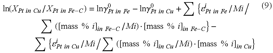
[0088]5 grams of carbon-saturated iron, 5 grams of a combination of a copper-neodymium alloy and copper in predetermined different proportions in order to vary the neodymium concentration in the copper, and 0.05 grams of platinum were placed into a graphite crucible. Using an electric furnace, the mixture was melted at 1823 K in an atmosphere of 100 ml / min of argon gas (converted to standard conditions) and held for 2 hours. The sample was then removed from the furnace and cooled by blowing argon gas.

[0089]Table 4 shows the neodymium concentration in the copper phase [mass % Nd]in Cu and the neodymium concentration in the iron phase [mass % Nd]in Fe-C in the sample after cooling, and the distribution ratio of neodymium [mass % Nd]in Cu / [mass % Nd]in Fe-C. FIG. 2 shows the results of plotting this data with the neodymium concentration in the copper phase on the abscissa and the common logarithm of the distribution ratio of neodymium on the ordinate.

TABLE 4[mass % Nd]in Cu0.40.573.597...


PUM

PropertyMeasurementUnit
Percent by massaaaaaaaaaa
Concentrationaaaaaaaaaa

Abstract

A method for efficiently recovering a platinum group element comprises melting copper-iron scrap containing a platinum group element, forming the melt into two liquid phases, a molten copper phase containing at least one rare metal selected from the group consisting of Nd, Pr, and Dy and a molten iron phase having a carbon concentration of at least 1 mass %, with the carbon contained in the molten iron phase being derived from carbon contained in the melt, separating the two liquid phases, recovering the molten copper phase, and separating and recovering from the molten copper phase a platinum group element dissolved therein. The copper-iron scrap may contain a rare metal, or a member containing a rare metal may be added to the melt with a preferred total concentration of rare metals in the melt being at least 1 mass %.

Description

TECHNICAL FIELD[0001]This invention relates to a method in which scrap containing copper and iron (referred to in this description as copper-iron scrap) and further containing a platinum group element typified by platinum (Pt) is separated into a molten copper phase containing neodymium (Nd), dysprosium (Dy), and / or praseodymium (Pr) (these metals will be collectively referred to below as rare metals) and a molten iron phase containing carbon in a predetermined concentration and the platinum is separated and recovered by concentrating the platinum contained in the copper-iron scrap in the molten copper phase with a high distribution ratio.BACKGROUND ART[0002]Various types of products including metal products made of iron and steel, copper, copper alloys and the like such as industrial equipment, transport equipment such as automobiles, household electrical appliances, office automation equipment, and electrical equipment, plastic products, and other types of products are manufacture...

Claims


Application Information

Patent Timeline
IPC IPC(8): C22B3/00
CPCC22B7/003C22B11/02C22B11/025C22B11/042C22B59/00Y02P10/20C22B7/00C22B9/02
Inventor NAKAMOTO, MASASHIYAMAMOTO, TAKAIKU
Owner NIPPON STEEL CORP
Why Eureka
Try Eureka