
Drill Bit For A Rock Drilling Tool With Increased Toughness And Method For Increasing The Toughness Of Such Drill Bits

a drill bit and drill bit technology, which is applied in the direction of grinding machines, furnaces, furnace types, etc., can solve the problems of reducing the service life of drilling tools, so as to increase the treatment energy and reduce the use of drilling tools. the effect of brittleness and low toughness

Active Publication Date: 2013-07-18
EPIROC DRILLING TOOLS AB
View PDF8 Cites 3 Cited by
  • Summary
  • Abstract
  • Description
  • Claims
  • Application Information

AI Technical Summary

Benefits of technology

The treatment method described in this patent results in stronger and more durable drill bits, reducing the number of ruptures and increasing their lifespan. This makes them more versatile and suitable for drilling in more materials, such as hard rock. The treatment involves colliding the components of the drill bit together, which can be done by thrusting them against each other and achieving the desired energy level. If the components are too low in mass, additional components (dummies) may be added to increase the energy and prevent edge damage. The treatment can also remove drill bit fragments to prevent damage to the bit during treatment. Additionally, the treatment speed can be increased during the process to further strengthen the drill bit.

Problems solved by technology

Such composite material therefore has such hardness that it is considered to be too hard and brittle to be used when drilling in hard rock, typically quartz rock.
In these cases the drill bits unfortunately wear out much more quickly and the drilling tool has a shorter lifetime.
Furthermore, the authors of the patent claim that the method substantially increases the surface hardness of treated components.

Method used


Image

  • Drill Bit For A Rock Drilling Tool With Increased Toughness And Method For Increasing The Toughness Of Such Drill Bits
  • Drill Bit For A Rock Drilling Tool With Increased Toughness And Method For Increasing The Toughness Of Such Drill Bits
  • Drill Bit For A Rock Drilling Tool With Increased Toughness And Method For Increasing The Toughness Of Such Drill Bits

Examples


Embodiment Construction

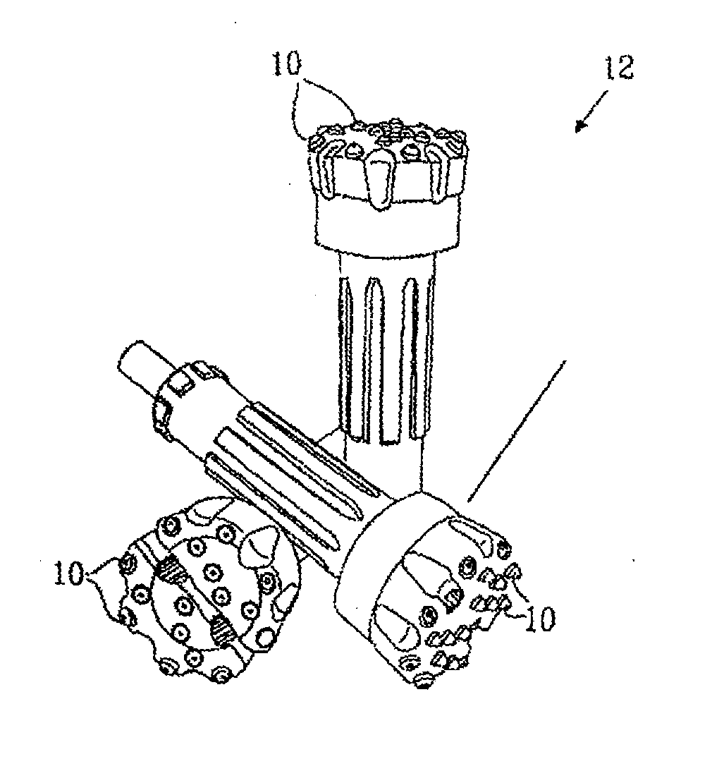
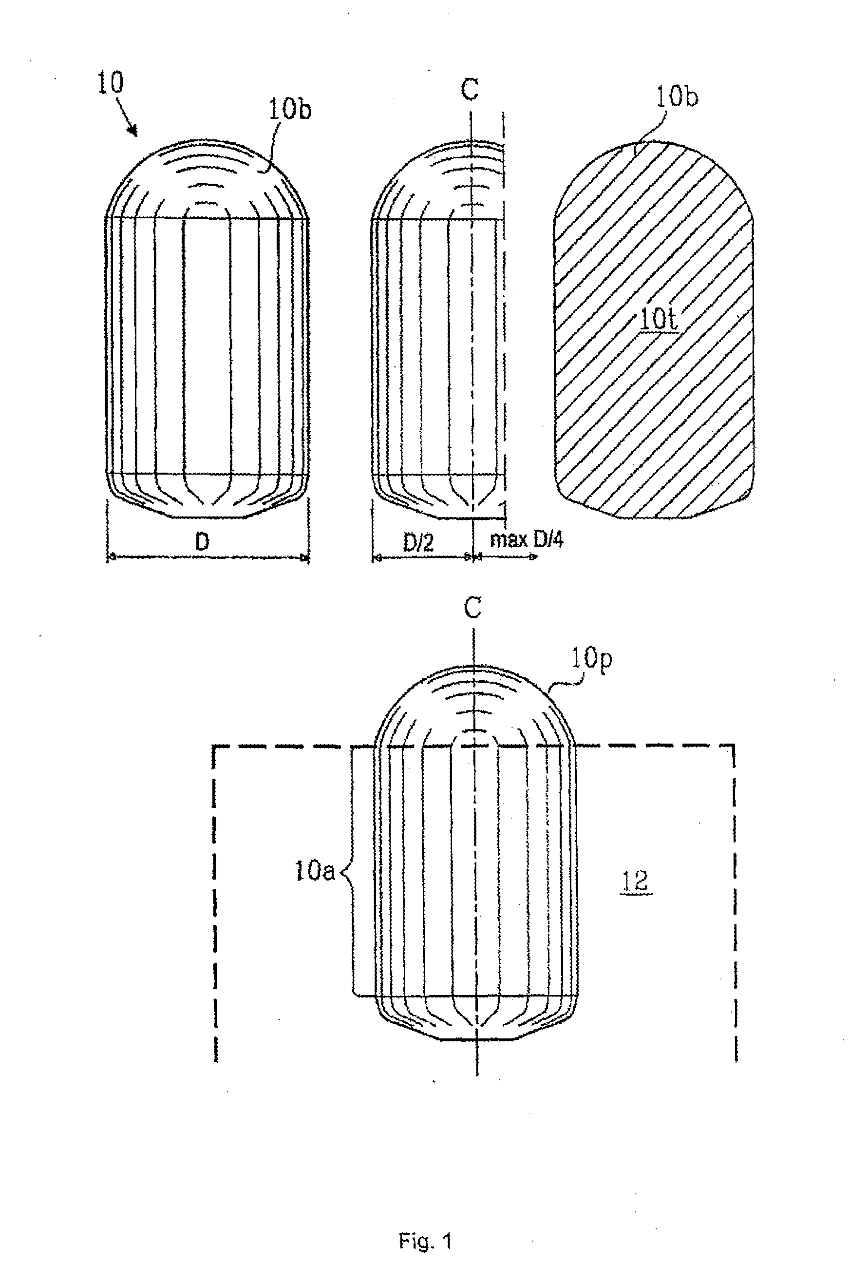
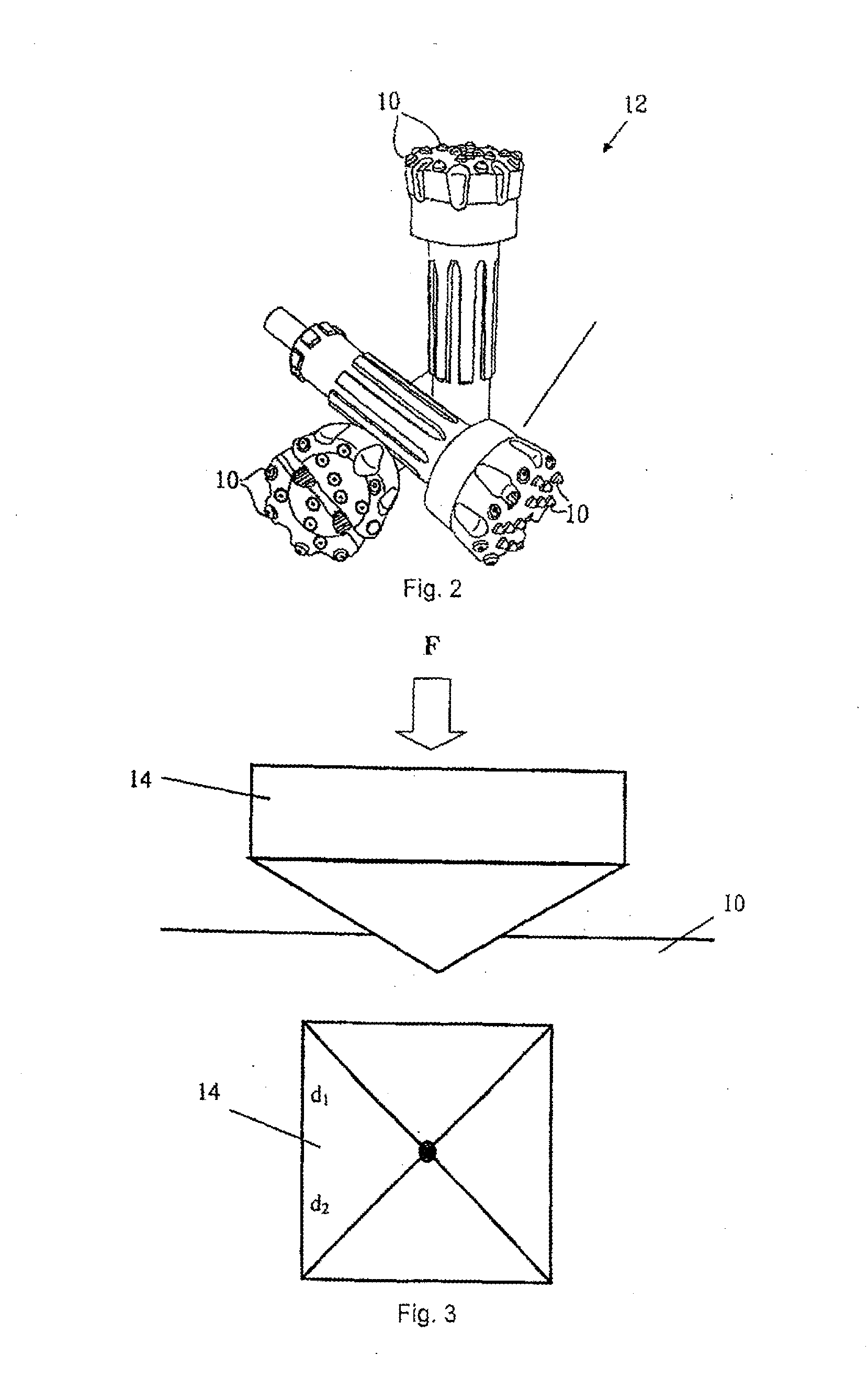
[0086]FIG. 1 shows a drill bit 10 embedded in a drill head of a rock drilling tool 12. Drill bits 10 have a cylinder-like part 10a with a diameter D of, for example, 16 mm, and a dome-like end profile 10p projecting from the drill head whose outer edge defines a drilling surface 10b. The end profile lop can however be semi-ballistic, semi-spherical, semi-cylindrical or of some other desired shape.

[0087]According to an embodiment of the invention the drill bit 10 has a diameter (D) of 7 mm or greater, or a mass of 5 grams or greater and it comprises sintered carbide, with tungsten carbide grains with an average particle size of 2.5 micrometres and 6% binder phase of cobalt or tungsten carbide grains joined with a binder phase of 3-12% cobalt, preferably 6-2.5% cobalt with an average particle size of up to 10 micrometres, preferably between 0.5 to 5.0 micrometres and more preferably from 1.5 to 3.5 micrometres.

[0088]Ltot(depth) and H(depth) have been measured at different depths, subs...


PUM

PropertyMeasurementUnit
particle sizeaaaaaaaaaa
lengthaaaaaaaaaa
lengthaaaaaaaaaa

Abstract

Drill bit (10) for a rock drilling tool (12), and a method of increasing the toughness of the drill bit, which drill bit (10) has a drilling surface (10b) that contacts rock during drilling. A longitudinal cross section (10t) of the drill bit (10) through the drilling surface (10b) exhibits certain relationships of Ltot(depth) / Ltot(5.0) and H(depth) / H(5.0) at the specified depths, along the drill bit's longitudinal axial center line (C) if the drill bit has a length (L) of 10 mm or greater, and Ltot(depth) / Ltot(3.5) and H(depth) / H(3.5) at the specified depths, if the drill bit has a length (L) of 10 mm or less.

Description

[0001]The present patent application is a divisional of U.S. Ser. No. 12 / 736,135, filed Sep. 13, 2010 (currently pending), which claims the benefit of PCT / SE2009 / 050219, filed Feb. 27, 2009, pursuant to 35 U.S.C. 371, which claims the benefit of Swedish Patent Application SE 0800721-3, filed Mar. 31, 2008, pursuant to 35 U.S.C. 119 (a).TECHNICAL FIELD[0002]The present invention concerns a drill bit for a rock drilling tool. The present invention also concerns a rock drilling tool and a method for treating drill bits for a rock drilling tool.BACKGROUND OF THE INVENTION[0003]A drilling tool comprising drill bits for rock drilling usually comprises a plurality of drill bits, made out of a hard material, embedded in a drilling head of relatively softer material, such as steel. The drill bits usually have a cylinder-like part that is embedded in the steel and a dome-shaped end profile that projects from the steel.[0004]Such drill bits are usually manufactured from a composite material, c...

Claims


Application Information

Patent Timeline
Patent Type & Authority Applications(United States)
IPC IPC(8): B24B31/00B24B31/06B24B31/02
CPCC21D7/04C21D9/22C22C29/02B24B31/06B24B31/00B24B31/02E21B10/56B22F3/24
Inventor CARLSSON, JIMMYSTENBERG, GORANREHNSTROM, MATTIAS
Owner EPIROC DRILLING TOOLS AB
Learn More