Method of transforming hfc CATV analog fiber transmission to digital fiber transmission

a technology of hfc catv and analog fiber, applied in the field of transforming hfc catv analog fiber transmission to digital fiber transmission, can solve the problems of inability to optimize the optical version of the basic rf catv waveform to cope with the available optical fiber spectrum, and achieve the effect of minimizing the burden of writing and minimizing the cost of transitioning

Active Publication Date: 2013-07-25
VECIMA NETWORKS
View PDF6 Cites 78 Cited by
  • Summary
  • Abstract
  • Description
  • Claims
  • Application Information

AI Technical Summary

Benefits of technology

[0009]The invention is based, in part, on the insight that by shifting to alternative types of waveforms, such as the waveforms used to transmit Gigabyte Ethernet (GigE) signals (which often use more distortion resistant waveforms such as binary phase shift keyed (BPSK) or quadraphase-shift keying (QPSK) modulation), a much higher amount of data may be sent over the optical fiber. The rate of data transmission per wavelength can be much higher, and different wavelengths may be spaced much closer together. Other benefits, such as lower noise level, and less power utilization, may also be realized.
[0011]The invention is also based, in part, on the insight that to minimize the cost of transitioning to a next-generation digital optical fiber based HFC system, those solutions that at least initially preserve large portions of legacy HFC systems, while also providing the benefits of digital optical fiber transmission, will often be preferable. In particular, “plug-in” head-end solutions, which enable legacy HFC head end systems to continue to operate by generating various RF waveforms at the head end, but which then efficiently demodulate or digitize these RF waveforms for optical fiber transmission have benefits in this regard. These “plug-in” head end solutions will work in conjunction with “plug-in” optical fiber node solutions that can then also efficiently remodulate, or digital to analog convert, the digital optical fiber data back into various RF waveforms suitable for injection into neighborhood CATV cable. Such “plug-in” solutions can, for example, minimize the burden of writing new management software because the process of demodulating or digitizing RF waveforms, although of course requiring some hardware for this purpose, is from a software perspective relatively simple. Even the process of compressing and decompressing this data before and after digital optical fiber transmission is also relatively simple. Similarly the process of taking the optically transmitted demodulated data or digitized data and in turn using it to modulate various CATV RF transmitters (or digital to analog converters) at the optical fiber node, although again requiring some new optical fiber node hardware, is also not complex from the software perspective. To the operator of the HFC system, the transition to digital optical fiber transmission can be, at least at first, almost totally transparent. The operator can continue to operate the head end using legacy software and systems, yet reap the benefits of digital optical fiber data transmission.
[0012]An additional advantage is that once suitable next generation digital fiber optic nodes (DOFN) are in place, the HFC system operator then gains the freedom to make additional head end improvements. In particular, legacy equipment that generates head end RF waveforms can gradually be phased out, and the head end equipment eventually be replaced with equipment that simply transmits digital data to the various CATV digital optical fiber nodes, according to a schedule that makes sense to the HFC system operator. The invention thus provides a gentle path that allows a legacy HFC system to be upgraded to a more efficient and more flexible all-digital (at least prior to the actual neighborhood CATV cable, which may still rely on RF waveforms as desired) system as a gradual series of steps.

Problems solved by technology

Although these direct RF to optical and back to RF waveform reproduction methods have the advantage of simplicity, due to various optical fiber signal propagation effects, such as Raman scattering, such RF to optical shifted CATV waveforms make inefficient use of available optical fiber spectrum.
This is because due to these various optical fiber effects, the various waveforms become smeared or distorted, resulting in crosstalk between neighboring optical fiber wavelengths, and the optical versions of the basic RF CATV waveforms are not at all optimized to cope with these effects.

Method used


Image

  • Method of transforming hfc CATV analog fiber transmission to digital fiber transmission
  • Method of transforming hfc CATV analog fiber transmission to digital fiber transmission
  • Method of transforming hfc CATV analog fiber transmission to digital fiber transmission

Examples


Embodiment Construction

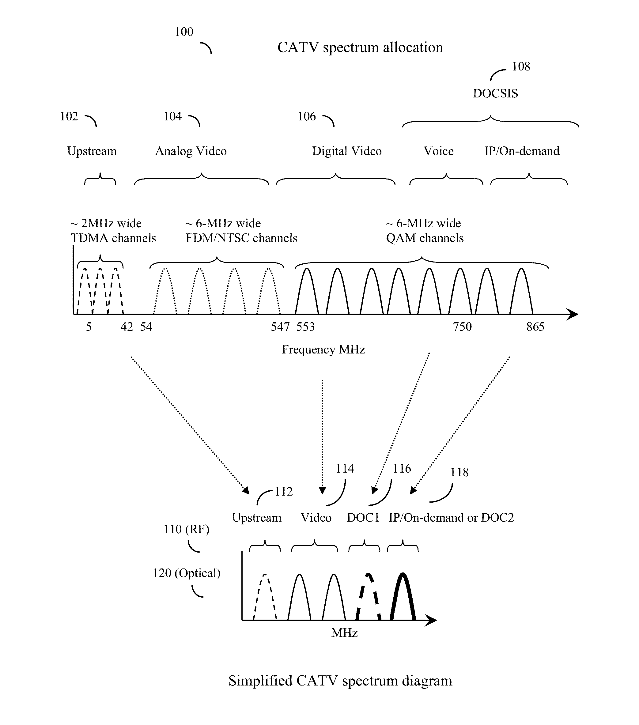
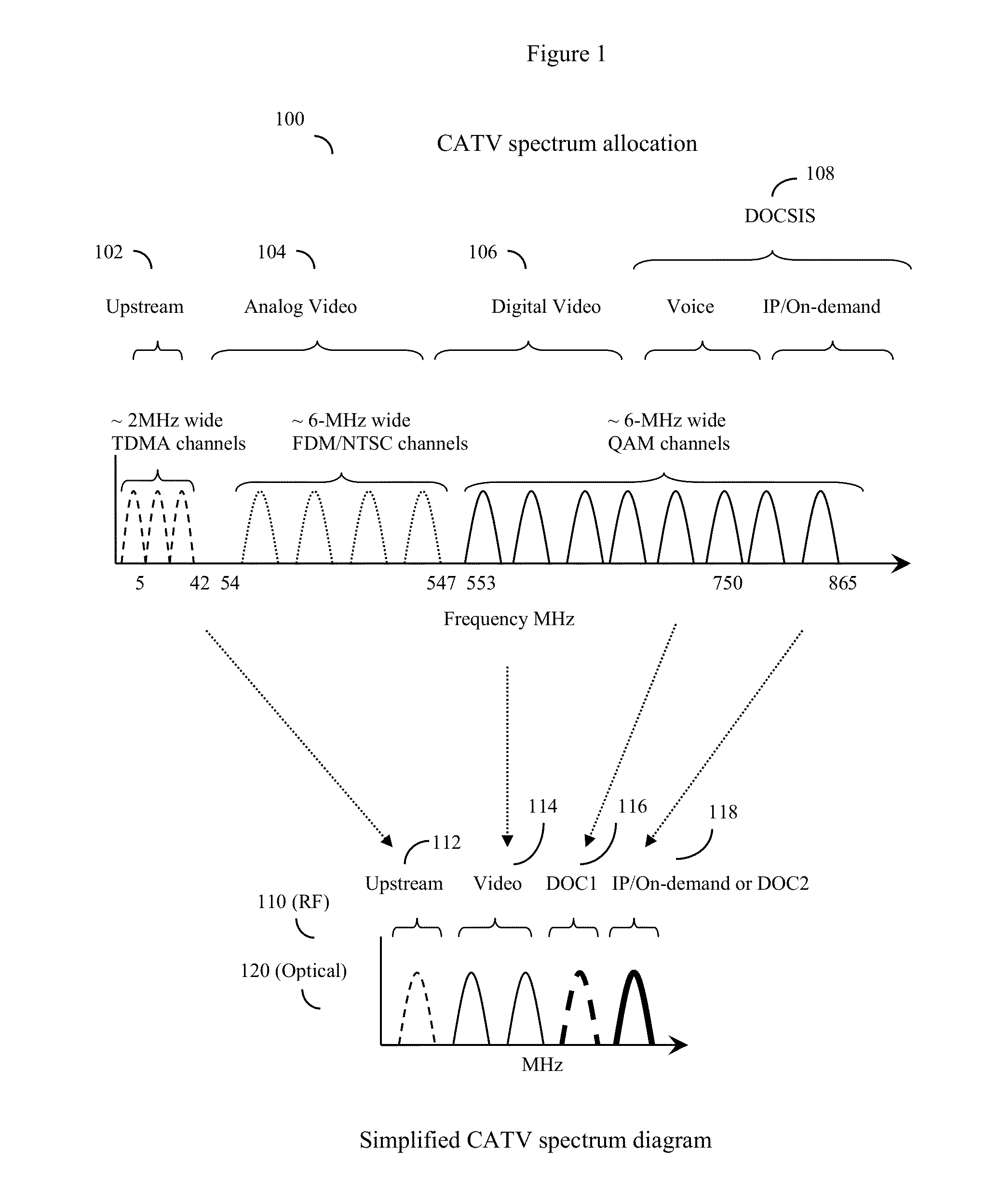
[0026]Nomenclature: In this specification, the term “legacy signals” when pertaining to RF waveforms, will often be used to describe various older standard CATV RF signals such as NTSC (television) signals, FM radio signals, set top box signals and the like. It should be understood, however, that the invention's methods will in fact operate with any type of RF signal. Thus the term legacy signals, although intended to improve readability by reminding the reader that the invention's methods are particularly useful for coping with various CATV legacy RF waveforms, is not otherwise intended to be limiting.

[0027]Legacy signals, when pertaining to optical fiber transmission methods, will generally refer to prior art methods which simply transformed the RF waveforms, such as QAM RF waveforms, into optical waveforms while retaining the essential characteristics (e.g. shape) of the RF waveforms.

[0028]Continued Discussion:

[0029]Although this particular specification is more focused on the op...


PUM


Abstract

A method of converting legacy HFC CATV cable systems, which transmit data over the optical fiber portion of the system using the optical counterpart of analog RF waveforms, such as RF QAM waveforms transduced to corresponding optical QAM waveforms, to improved HFC CATV systems that transmit data over the optical fiber using optical fiber optimized protocols, such as Ethernet frames and other optical fiber optimized digital transport protocols. According to the method, most aspects of the legacy HFC CATV system may be retained, however at the CATV head end, the optical fiber transmitter system is replaced by an improved system that extracts the underlying symbols from legacy waveforms, packages these symbols into optical fiber optimized packets, and transmits downstream. The legacy optical fiber nodes are replaced with improved nodes capable of receiving the packets and remodulating the symbols into RF waveforms suitable for injection into the system's CATV cable.

Description

CROSS REFERENCE TO RELATED APPLICATIONS[0001]This application is a continuation in part of U.S. patent application Ser. No. 13 / 674,936, “HYBRID ALL DIGITAL FIBER TO CATV CABLE SYSTEM AND METHOD”, filed Nov. 12, 2012; this application is also a continuation in part of application Ser. No. 13 / 555,170, “DISTRIBUTED CABLE MODEM TERMINATION SYSTEM WITH SOFTWARE RECONFIGURABLE MAC AND PHY CAPABILITY”, filed Jul. 22, 2012, which in turn claimed the priority benefit of U.S. provisional application 61 / 511,395, “IMPROVED HYBRID FIBER CABLE SYSTEM AND METHOD”, filed Jul. 25, 2011, and which was also a continuation in part of application Ser. No. 13 / 035,993, “METHOD OF CATV CABLE SAME-FREQUENCY TIME DIVISION DUPLEX DATA TRANSMISSION”, filed Feb. 27, 2011, now U.S. Pat. No. 8,365,237; this application is also a continuation in part of U.S. patent application Ser. No. 13 / 478,461, “EFFICIENT BANDWIDTH UTILIZATION METHODS FOR CATV DOCSIS CHANNELS AND OTHER APPLICATIONS”, filed May 23, 2012, which i...

Claims


Application Information

Patent Timeline
Patent Type & Authority Applications(United States)
IPC IPC(8): H04N21/61
CPCH04N21/6118H04L27/2601H04L27/3405H04B10/25751H04L12/2801H04N7/10H04H20/78H04N7/22H04N21/2221H04N21/615H04N21/6168H04H20/06H04H20/69H04N7/17309H04N21/2383H04N21/2385H04N21/239
Inventor RAKIB, SHLOMO SELIM
Owner VECIMA NETWORKS
Why Eureka
Try Eureka