Balloon design to enhance cooling uniformity

a balloon and uniform cooling technology, applied in the field of balloon design to enhance can solve the problems of increasing the risk of balloon getting deep in the vein, pulmonary vein stenosis or other vascular damage, and achieve the effect of enhancing the uniformity of cooling and the efficiency of cryogenic fluids

Active Publication Date: 2013-08-01
MEDTRONIC CRYOCATH LP
View PDF9 Cites 41 Cited by
  • Summary
  • Abstract
  • Description
  • Claims
  • Application Information

AI Technical Summary

Benefits of technology

[0008]The present invention advantageously provides a device, system, and method for not only enhancing cooling uniformity and efficiency of cryogenic fluids, but also changing the shape of a cryoablation treatment element to serve multiple purposes. The device may comprise: a cooling chamber including an interior wall and an exterior wall; a coolant delivery element disposed within the cooling chamber; and a coolant distribution element disposed within the cooling chamber that guides coolant delivered from the coolant delivery element toward the interior wall of the cooling chamber. The cooling chamber may be a balloon. The coolant distribution element may be a membrane disposed within the cooling chamber so as to divide the cooling chamber into a first portion and a second portion, the coolant delivery element being within the first portion and the membrane allowing transit of coolant from the first portion to the second portion. Further, the membrane meters transit of coolant from the first portion to the second portion, and may be at least one of: gas permeable; liquid permeable; and combination thereof. Further, the membrane includes a plurality of apertures. The apertures may be located proximate the interior wall of the cooling chamber. Further, the membrane may includes a first edge and a second edge, the first edge being in contact with a portion of the interior wall of the cooling chamber. The first edge may be affixed to the interior wall of the cooling chamber.

Problems solved by technology

However, ablating tissue with a balloon shape that is optimal for occlusion, such as a teardrop shape, may increase the risk of the balloon getting deep in the vein and leading to pulmonary vein stenosis or other vascular damage.

Method used


Image

  • Balloon design to enhance cooling uniformity
  • Balloon design to enhance cooling uniformity
  • Balloon design to enhance cooling uniformity

Examples


first embodiment

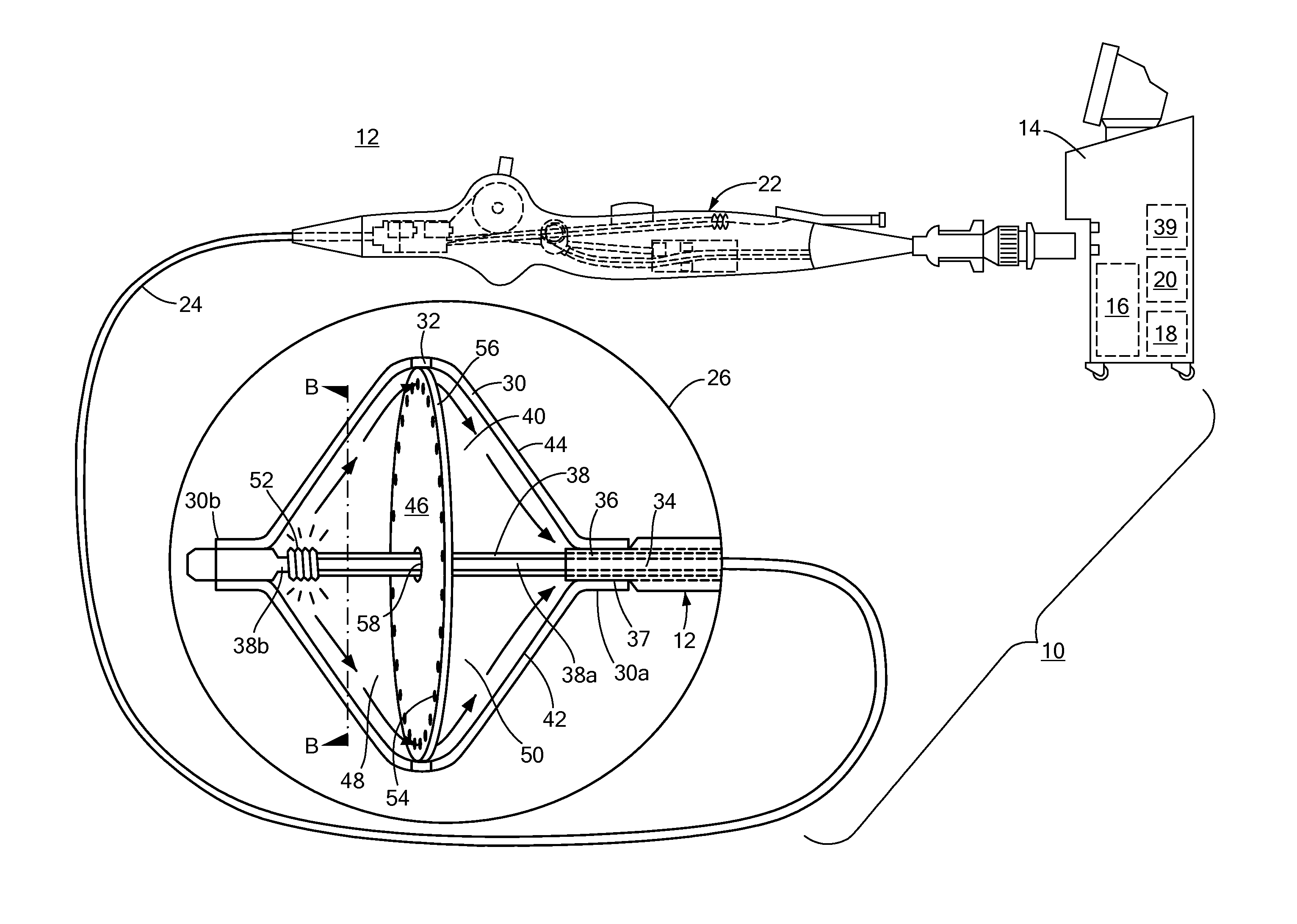
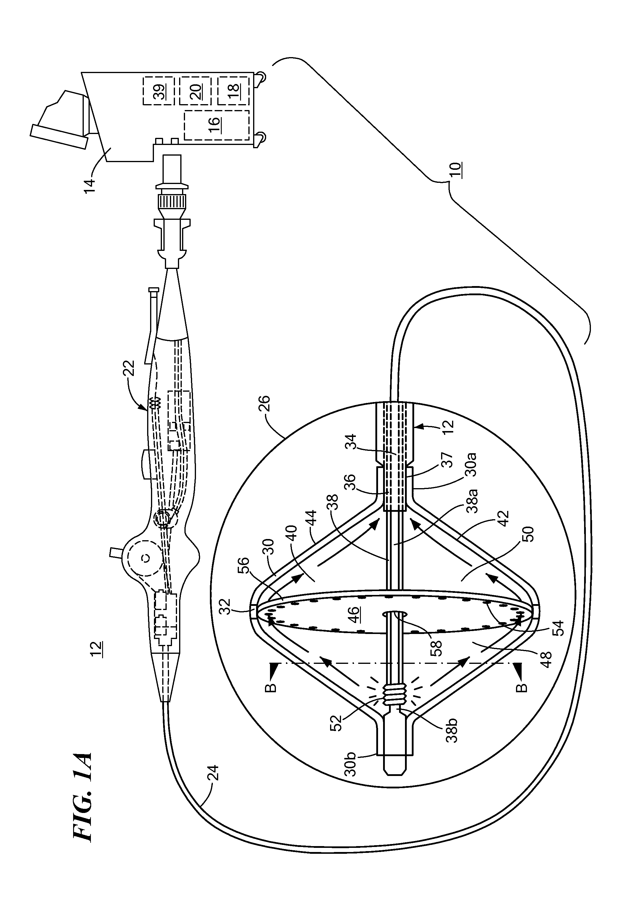
[0027]Referring now to FIG. 1A, a system including a cryoablation treatment element is shown. The system 10 generally includes a device 12 for treating tissue and a console 14 that houses various system controls. The system 10 may be adapted for both radiofrequency ablation (RFA) and cryoablation. The console 14 may include one or more of a coolant reservoir 16, coolant return reservoir 18, and RF generator 20, and may further include various displays, screens, user input controls, keyboards, buttons, valves, conduits, connectors, power sources, and computers for adjusting and monitoring system parameters.

[0028]Continuing to refer to FIG. 1A, the device 12 may be an ablation device generally including a handle 22, an elongate body 24 having a distal end 26 and one or more treatment elements. The handle 22 may include various knobs, levers, user control devices, input ports, outlet ports, connectors, lumens, and wires. The one or more treatment elements may be expandable elements suc...

second embodiment

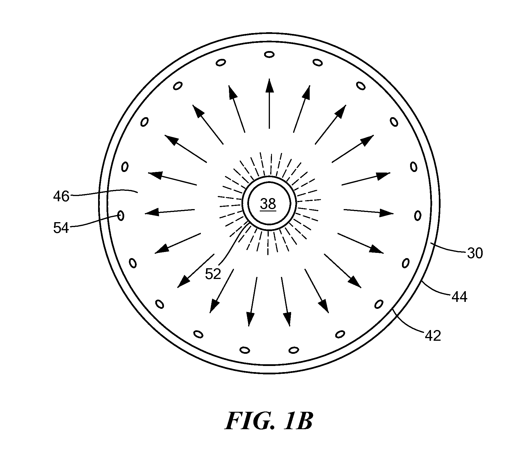
[0033]Referring now to FIGS. 2A and 2B, cross-sectional views of a cryoablation treatment element are shown. FIG. 2B shows the first portion 48 of the cooling chamber 40 as taken along axis B-B in FIG. 1A. Like FIGS. 1A and 1B, the treatment element of FIGS. 2A and 2B is a balloon 30 defining a cooling chamber 40 having a first portion 48 and a second portion 50. The balloon 30 further includes an FDE 46 that is a membrane having a plurality of apertures 54. In FIGS. 2A and 2B, the fluid injection element 52 is integrated with the shaft 38, rather than being a separate element disposed about the shaft 38, as shown in FIGS. 1A and 1B. In this embodiment, the fluid injection lumen 36 is within the shaft 38 and the shaft 38 includes a plurality of apertures or outlet ports in fluid communication with the fluid injection lumen 36. Expanded coolant flows from the second portion 50 into the fluid return lumen 37. The cross section shown in FIG. 2B is along the B-B axis shown in FIG. 2A. T...

third embodiment

[0034]Referring now to FIG. 3, a cross-sectional view of a cryoablation treatment element is shown. Like FIG. 1A, the treatment element of FIG. 3 is a balloon 30 defining a cooling chamber 40 and having an interior wall 42 and an exterior wall 44. The balloon 30 further includes an FDE 46 disposed within the cooling chamber 40, dividing the cooling chamber 40 into a first portion 48 and a second portion 50. Unlike the membrane 46 of FIG. 1A, the FDE 46 of FIG. 3 is not in contact with the interior wall 42 of the balloon 30. Rather, the FDE 46 in FIG. 3 is a second balloon 62 of smaller size than the balloon 30 (“first balloon 30”). The second balloon 62 includes a plurality of apertures 64, and the fluid injection element 52 is located within the second balloon 62. The fluid injection element of FIG. 3 is shown as being integrated with the shaft 38 (as shown in FIG. 2A), but could also be disposed about or adjacent to the shaft 38 (as shown in FIG. 1A). The apertures 64 of the secon...


PUM


Abstract

A device, system, and method for enhancing cooling uniformity and efficiency of cryogenic fluids and providing a treatment element the shape of which can be adjusted for multiple purposes. The device may include a balloon catheter and fluid dispersion element, the fluid dispersion element directing the flow of coolant from a fluid injection element the interior wall of the balloon. The method of changing the shape of the treatment element may include retracting and extending a shaft to which the distal neck of a balloon is coupled, so that the balloon goes from a first shape to a second shape.

Description

CROSS-REFERENCE TO RELATED APPLICATION[0001]n / aSTATEMENT REGARDING FEDERALLY SPONSORED RESEARCH OR DEVELOPMENT[0002]n / aFIELD OF THE INVENTION[0003]The present invention relates to a method and system for BACKGROUND OF THE INVENTION[0004]Cryoablation therapy is a technique that uses freezing to locally destroy or alter body tissue, such as a tumor, cardiac tissue associated with arrhythmia, or diseased or congenitally abnormal tissue. Surgical cryoprobes and cryoablation catheters are typically used to perform this technique, and may generally include a power source, a coolant source, and one or more treatment elements. Commonly used cryoablation treatment elements include expandable elements (for example, balloons) through which cryogenic fluid, such as a phase-change coolant, circulates. The temperature of phase-change coolants is lowered via the Joule-Thomson effect, which occurs when the coolant expands within the treatment element.[0005]When the treatment elements of the cathete...

Claims


Application Information

Patent Timeline
Patent Type & Authority Applications(United States)
IPC IPC(8): A61B18/02
CPCA61B18/02A61B18/1492A61B2018/0022A61B2018/00255A61B2018/00375A61B2019/464A61B2018/00791A61B2018/00994A61B2018/0212A61B2018/0268A61B2018/00577A61B2018/00648A61B2018/0275A61B2090/064
Inventor LALONDE, JEAN-PIERREDAVIE, SCOTT W.WITTENBERGER, DAN
Owner MEDTRONIC CRYOCATH LP
Why Eureka
Try Eureka