Microblister skin grafting

a micro-blister and skin grafting technology, applied in the field of micro-blister skin grafting, can solve the problems of skin tissue being subject to many forms of damage, skin grafting involves certain risks, trauma and wound generation at the donor site, etc., and achieves the effect of improving design features and reducing patient harm and discomfor

Active Publication Date: 2013-08-08
3M INNOVATIVE PROPERTIES CO
View PDF9 Cites 84 Cited by
  • Summary
  • Abstract
  • Description
  • Claims
  • Application Information

AI Technical Summary

Benefits of technology

[0016]The present invention provides devices for generating and harvesting a skin graft having improved design features for ensuring sufficient and consistent blister formation and reducing patient harm and discomfort.
[0027]In a fifth aspect, the invention provides a device for generating and harvesting a skin graft having design features for ensuring the capture and transfer of blisters onto a substrate. Such devices include a mechanism for raising at least one blister, a hollow body configured for placement on skin, at least one plate member integrated within the body and including at least one hole through which the blister is raised, a substrate removably coupled to the plate member, and a substrate compression mechanism movably coupled to the body. The substrate compression mechanism includes an actuator member coupled to a compression member. Actuation of the compression mechanism removably couples the compression member onto the substrate to ensure full contact between the substrate and the raised blister.
[0029]The compression member is movably coupled to the hollow body via an axle, a hinge, or similar mechanism that allows the compression member to be removably applied to the substrate. The actuation member can be a handle coupled to the compression member to facilitate application of the compression member to the substrate.
[0051]At least one of the openings in the first, second or third plate defines a cutting surface. In certain embodiments, the cutting surface on one of the plates engages a cutting surface on at least one other of said plates in operation (i.e., when at least one of the plates is moved with respect to the other plates). In certain embodiments, the opening in at least one of the plates moves with respect to the openings in at least another of said plates, thereby to perform a cutting action.
[0061]At least a part of the harvester e.g., a top alignment plate, can be formed of a radiation absorbing material, such as a fluoropolymer surface coating or layer to enhance heating of the skin.
[0062]In another preferred embodiment, the harvester includes a top alignment plate and a bottom alignment plate and the cutting plate is disposed therebetween. The top and bottom alignment plates can be joined together by a plurality of vertical posts that pass through slots in the cutting plate to maintain the fixed position of the top and bottom plates relative to each other while permitting movement of cutting plate. The top plate, bottom plate and cutting plate can each have a plurality of holes that are adapted to be concentrically aligned to facilitate blister formation. In certain embodiments, the holes of the top plate are larger than the holes of the bottom plate.

Problems solved by technology

Skin tissue may be subject to many forms of damage, including burns, trauma, disease, and depigmentation (e.g., vitiligo).
As with any surgical procedure, skin grafting involves certain risks.
A problem encountered when using an autograft is that skin is taken from another area of a person's body to produce the graft, resulting in trauma and wound generation at the donor site.
Generally, the size of the graft matches the size of the recipient site, and thus a large recipient site requires removal of a large section of skin from a donor site, leading to increased pain and discomfort and longer healing time.
Additionally, as the size of the section of skin removed from the donor site increases, so does the possibility of infection.
Moreover, skin grafts are often difficult to obtain due to the tendency of the skin layer being cut to curl or fold over onto itself or the surgical instrument (e.g., dermatome), thereby comprising the integrity of the graft and making it unsuitable for use.
This folding / curling tendency is particularly problematic the thinner the layer is that is being obtained, such as the epidermal layer.
While techniques have been developed for obtaining smaller micrografts that can be transferred onto a substrate for expansion prior to transplantation, such micrografts tend to clump together or can flip or fold during cutting, thereby comprising the integrity of the micrograft such that it will not properly grow on the substrate.
As such, multiple cutting attempts are often necessary before a suitable, planar graft or micrograft is obtained, thereby producing multiple wound sites, leading to extreme discomfort, longer healing time, and a greater risk of infection.
The heat source of a suction blistering device can become overheated and burn out, causing inconsistent blister formation and potential harm to the patient.

Method used


Image

  • Microblister skin grafting
  • Microblister skin grafting
  • Microblister skin grafting

Examples


Embodiment Construction

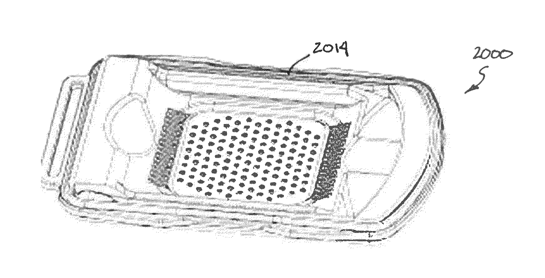
[0094]The present invention generally relates to a single device that can raise a blister (e.g., a suction blister) and cut the raised blister, i.e., a blister raising device integrated with a cutting member. Such devices are useful for harvesting skin grafts.

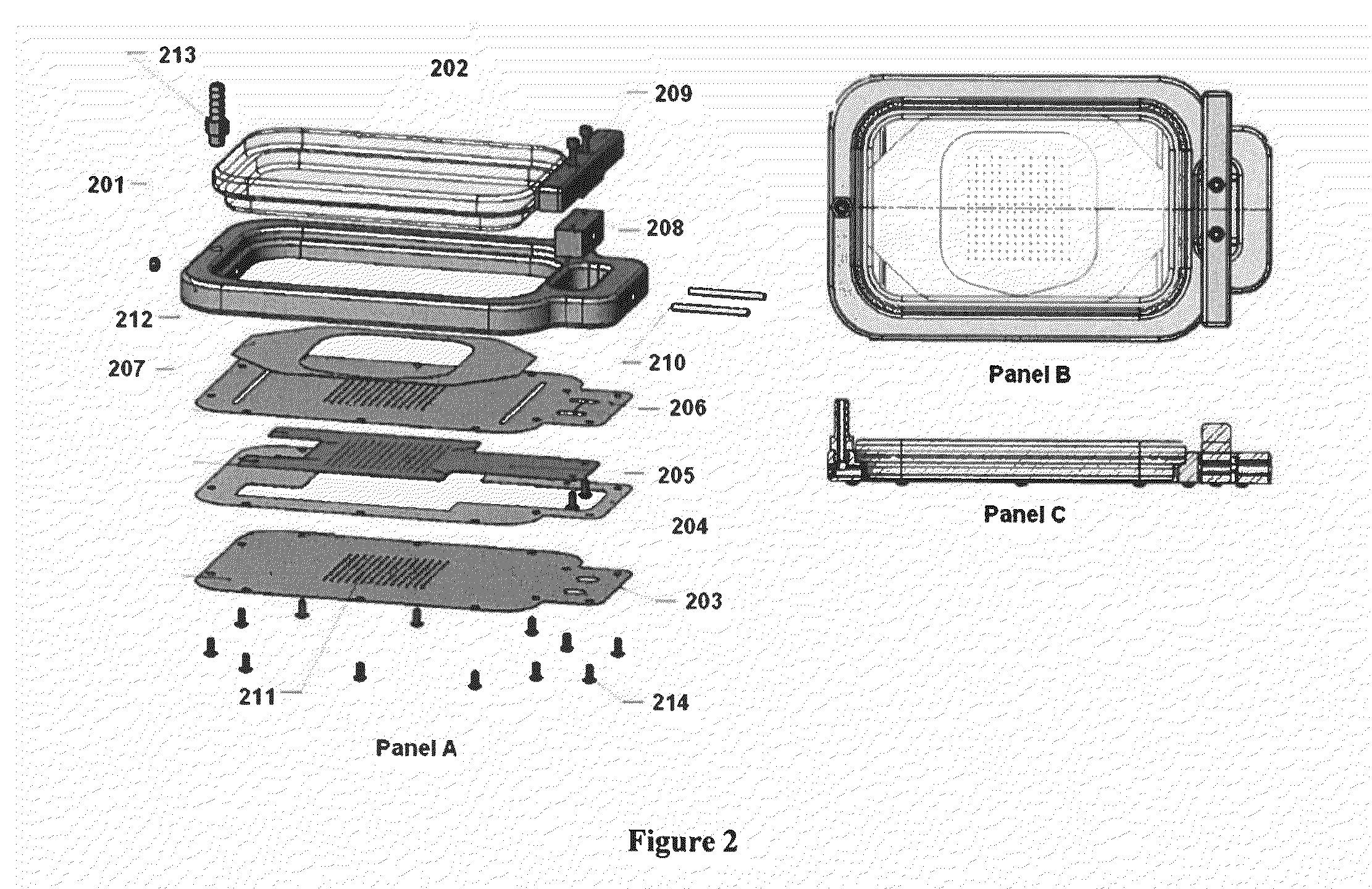
[0095]In certain embodiments, a device as shown in FIG. 2 panels A-C is used to raise and cut a plurality of skin grafts. Device 200 includes a frame 201 and a lid 202. Fitted into the frame is a bottom plate 203, a cutter grid plate 204, a cutter plate 205, and a top plate 206. The bottom plate 203, the cutter plate 205, and the top plate 206, each include a hole array 211. Once assembled, the hole array 211 of each of plates 203, 205, and 206 are aligned. The size of the holes in the hole array will depend on the size of the graft needed, with larger holes being used to produce larger grafts. A first substrate 207 interacts with the top plate 206 and will receive the harvested grafts.

[0096]Device 200 further includes an actua...


PUM


Abstract

The present invention generally relates to devices for harvesting a skin graft(s). The present invention provides a blister raising device integrated with a member for cutting the blister.

Description

REFERENCE TO RELATED APPLICATIONS[0001]This application claims the benefit of, and priority to, U.S. patent application Ser. No. 13 / 346,329 filed Jan. 9, 2012, which claims the benefit of and priority of U.S. Provisional Application No. 61 / 567,946, filed Dec. 7, 2011.[0002]This application also claims the benefit of, and priority to, U.S. patent application Ser. No. 13 / 436,318 also filed Jan. 9, 2012, which is a continuation-in-part of U.S. patent application Ser. No. 12 / 851,656 filed Aug. 6, 2010[0003]This application further claims the benefit of, and priority to, U.S. patent application Ser. No. 12 / 851,621 filed Aug. 6, 2010; U.S. patent application Ser. No. 12 / 851,703 filed Aug. 6, 2010; and U.S. patent application Ser. No. 12 / 851,682 filed Aug. 6, 2010.[0004]The contents of each of the above-referenced related application are herein incorporated by reference in its entirety.FIELD OF THE INVENTION[0005]The present invention generally relates to devices and methods for generating...

Claims


Application Information

Patent Timeline
Patent Type & Authority Applications(United States)
IPC IPC(8): A61B17/322
CPCA61B17/322A61B18/08A61B2017/00761A61B2017/3225A61B2018/00041A61B2018/00452A61B2018/0047A61B2018/00791A61B2018/1412
Inventor SABIR, SAMEER AHMEDZIEGLER, ANDREW
Owner 3M INNOVATIVE PROPERTIES CO
Why Eureka
Try Eureka