Method of controlling hydraulic machine to reduce torque ripple and/or bearing side load

a hydraulic machine and torque ripple technology, applied in the direction of positive displacement liquid engine, piston pump, fluid coupling, etc., can solve the problems of not addressing the bearing side load, unable to meet the demands of displacement, and completely lacking the advantages of infinitely variable displacement and rapid response to displacement demands. , to achieve the effect of reducing the transient torque ripple and reducing the torque rippl

Inactive Publication Date: 2013-08-15
MITSUBISHI HEAVY IND LTD
View PDF0 Cites 11 Cited by
  • Summary
  • Abstract
  • Description
  • Claims
  • Application Information

AI Technical Summary

Benefits of technology

[0040]The controller may be programmed to regulate the opening and / or closing time of at least one valve associated with each cylinder to vary the net displacement of working fluid by each cylinder during active cycles.
[0041]Accordingly, some variation in the net displacement of working fluid by the hydraulic machine, per cycle of the cam, is possible without changing the selection of one or more groups of cylinders. This enables the hydraulic machine to adapt to small changes in demand without having to change the pattern of cylinders which execute active cycles. This reduces the frequency of changes in the pattern of cylinders which execute active cycles and thereby reduces transient torque ripple which could occur when changes are made.
[0042]The invention also envisages that torque ripple may be reduced by suitable selection of the profile of cylinder volume with phase during a cycle of cylinder volume. The profile of cylinder volume with phase angle depends on several factors. Where cylinder volume is determined by pistons in driving engagement with a cam, the profile of cylinder volume with phase angle depends on the profile of the cam, the way in which the piston is driven by or drives the cam (for example, the size of a piston roller), the angle of the piston relative to the axis of rotation of the cam etc. This can readily be determine by inspection of the hydraulic machine.

Problems solved by technology

Bearing side load can be particularly high at some displacement levels which lead to forces being exerted predominantly by pistons driven by cylinders located adjacent each other and therefore exerting forces which sum to a high resultant force.
However, there can be difficulties with torque ripple changing when one pattern is completed and the next begins and this does not address bearing side load, particularly as the pre-calculated patterns are preferably relatively short.
This technology requires a period of multiple cycles of cylinder volume to switch groups of cylinders on and off and so responds slowly compared to machines of the type described above, entirely lacking the advantages of infinitely variable displacement and rapid response to displacement demands.
Furthermore, the grouping of cylinders is fixed, and cannot be changed.

Method used


Image

  • Method of controlling hydraulic machine to reduce torque ripple and/or bearing side load
  • Method of controlling hydraulic machine to reduce torque ripple and/or bearing side load
  • Method of controlling hydraulic machine to reduce torque ripple and/or bearing side load

Examples


Embodiment Construction

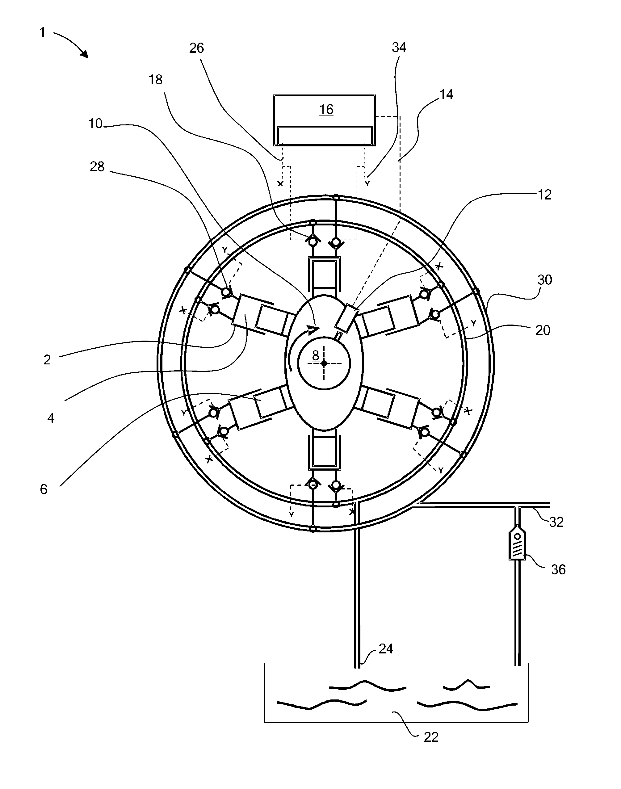
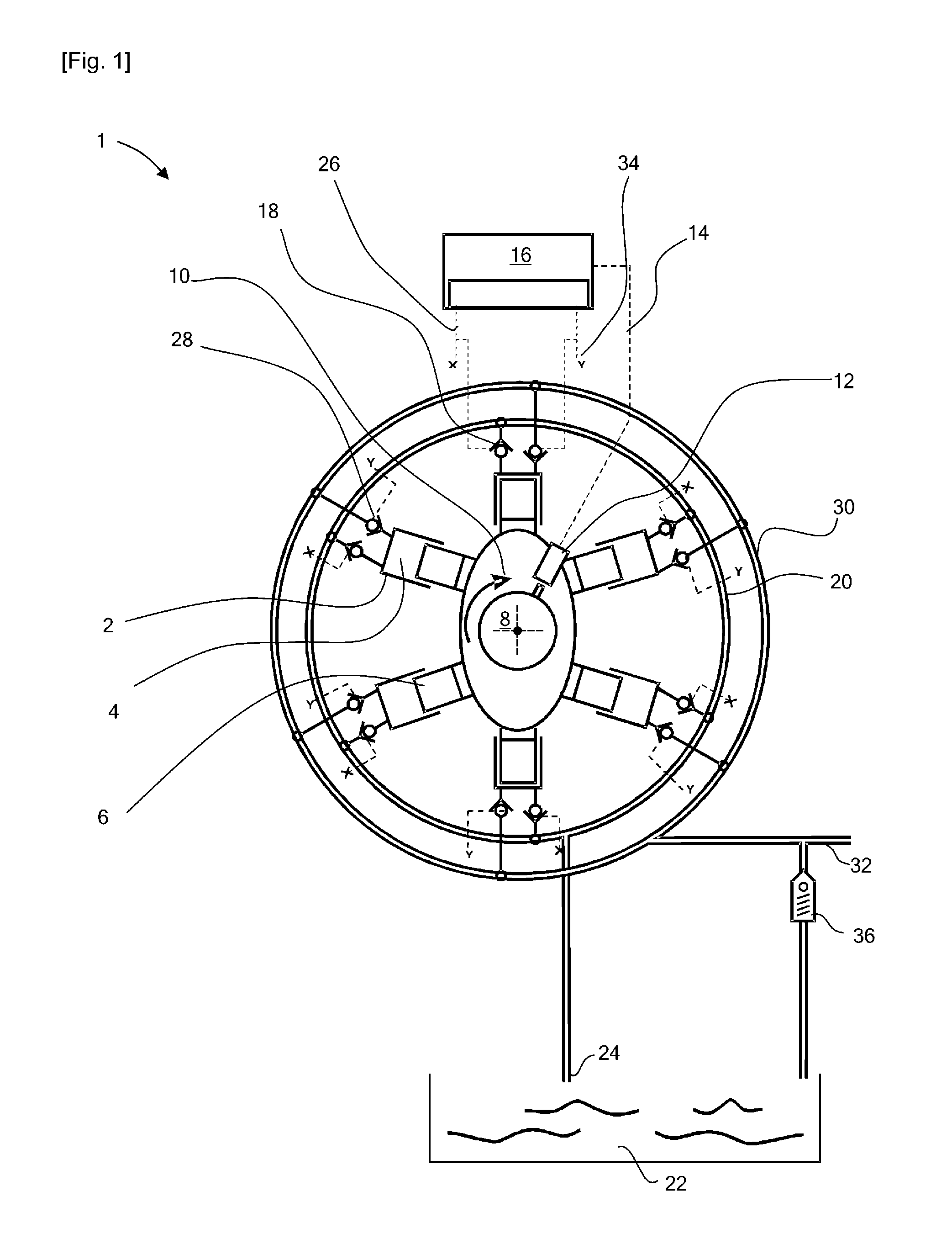
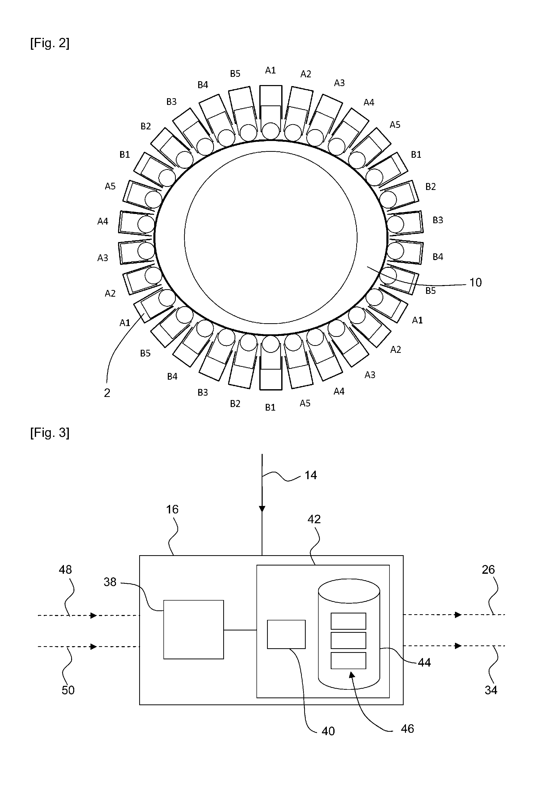
[0071]FIG. 1 illustrates a fluid working machine in the form of an electronically commutated hydraulic pump / motor 1 comprising a plurality of cylinders 2 having cyclically varying cylinder volumes 4 defined between the interior surface of the cylinders and respective pistons 6 which are driven from a rotatable crankshaft 8 by a multi-lobe eccentric cam 10 thereby reciprocating within the cylinders to cyclically vary the cylinder volumes. A shaft position and speed sensor 12 determines the instantaneous angular position and speed of rotation of the shaft, and through signal line 14 informs a controller 16, which enables the controller to determine the instantaneous phase angle of the cycles of each cylinder. The controller is typically a microprocessor or microcontroller which executes a stored program in use and is described further below with reference to FIG. 3.

[0072]The cylinders are each associated with Low Pressure Valves (LPV) in the form of electronically actuated face-sealin...


PUM


Abstract

A hydraulic machine in which the volume of working fluid displaced by each cylinder is selectable on each cycle of working chamber volume by active control of one or more electronic valves has a controller configured to select specified groups of cylinders to repetitively carry out active cycles until a change in selection is made. The groups are selected to reduce torque ripple and/or bearing side load. The cam profile may be varied to further reduce torque ripple.

Description

TECHNICAL FIELD[0001]The invention relates to the field of large hydraulic machines suitable for use in applications such as a hydraulic transmission in a wind turbine generator, in which the volume of working fluid displaced by each cylinder on each cycle of cylinder volume is selectable by the control of electronically controlled valves.BACKGROUND ART[0002]It is known from EP 0 361 927 (Salter and Rampen) to operate a hydraulic pump in which each cylinder has an electronically controlled low pressure valve arranged to regulate the flow of working fluid from low pressure manifold into the respective cylinder and to control the electronically controlled valve on each cycle of cylinder volume to determine whether the cylinder undergoes a pumping cycle with a net displacement of working fluid, or an idle cycle with no net displacement of working fluid. EP 0 494 236 (Salter and Rampen) discloses an improvement in which the valve between each cylinder and the high pressure manifold (the...

Claims


Application Information

Patent Timeline
Patent Type & Authority Applications(United States)
IPC IPC(8): F15B15/20
CPCF15B15/20F04B7/0076F04B17/02F04B53/1082F04B49/225F04B49/243F04B49/246F04B49/065Y02P80/10
Inventor CALDWELL, NIALLDUMNOV, DANIILLAIRD, STEPHEN
Owner MITSUBISHI HEAVY IND LTD
Why Eureka
Try Eureka