Planar Transformers

a transformer and planar technology, applied in the field of planar transformers, can solve the problems of reducing the efficiency of the transformer and creating a temperature rise in the planar winding, and achieve the effect of improving the coupling between windings

Inactive Publication Date: 2013-08-15
MICROMASS UK LTD
View PDF4 Cites 38 Cited by
  • Summary
  • Abstract
  • Description
  • Claims
  • Application Information

AI Technical Summary

Benefits of technology

[0015]According to one aspect of the present invention, there is provided a planar transformer comprising one or more, e.g. two or more, preferably a plurality of conductive windings provided by at least one printed circuit board (PCB) and linked by a common ferrite core passing through the or each PCB, wherein the transformer windings or winding tracks and / or gaps therebetween are at least partially magnetically shielded from the ferrite core by a conductive non-continuous shield, e.g. thereby to improve the coupling between windings.
[0019]The windings and / or shielding may be remote from, e.g. spaced from or kept clear of the transformer magnetic gap, for example to minimize eddy current losses. Preferably, the clearance or space between the windings and / or shielding and the transformer magnetic gap is approximately, e.g. substantially, five times the length of the magnetic gap.

Problems solved by technology

The eddy currents developed in the planar winding will lead to additional power dissipation reducing the efficiency of the transformer and will create a temperature rise in the planar winding.
However, the stray magnetic flux which occurs around the ferrite and particularly around the magnetic gap cannot pass through the actual copper tracks making up the winding, but can pass between windings, or between the turns of multi-turn windings.

Method used


Image

  • Planar Transformers
  • Planar Transformers
  • Planar Transformers

Examples


Embodiment Construction

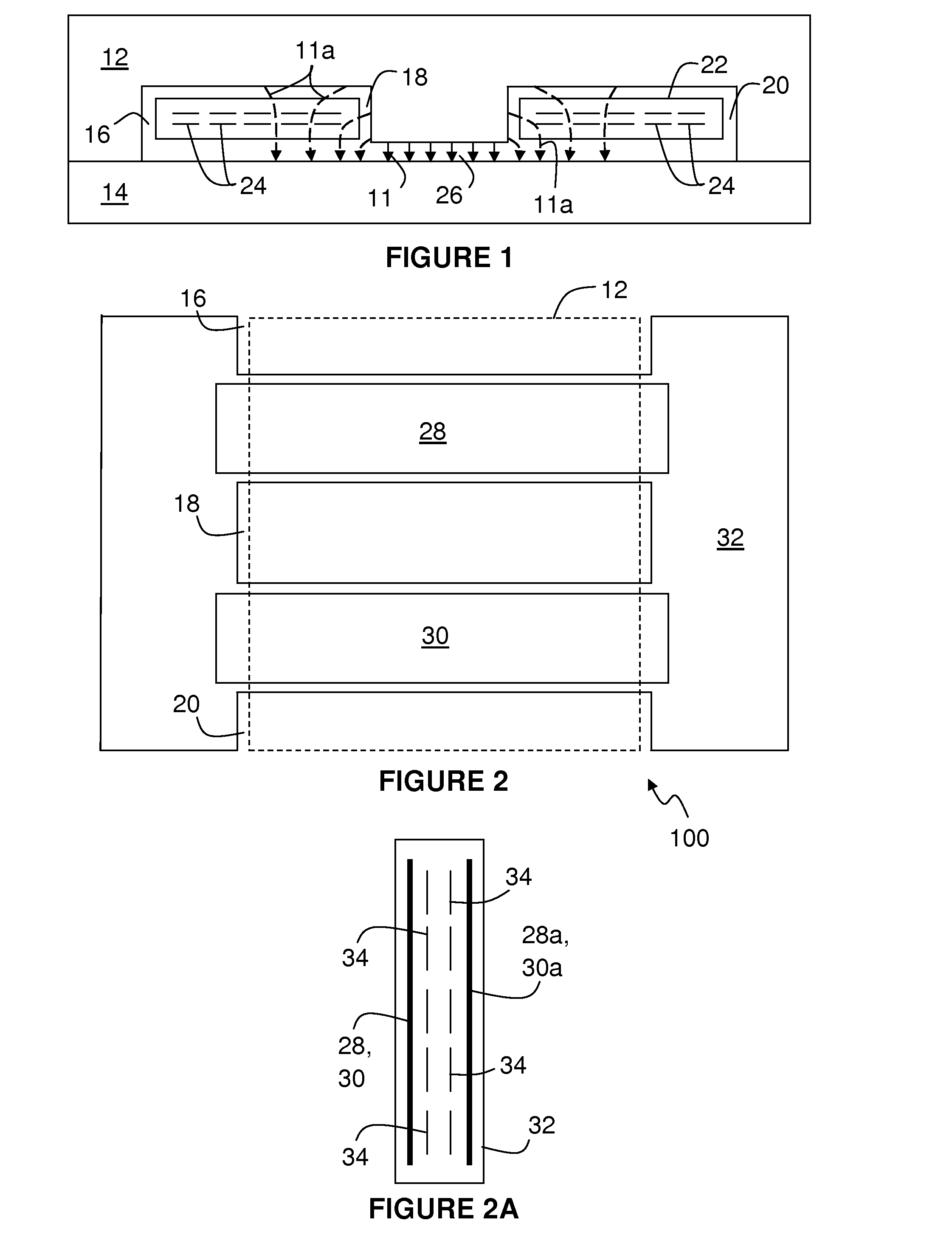
[0032]FIG. 1 is an end view of a planar transformer 10 with a ferrite core comprising an ‘E’-core 12 and an ‘I’-core 14. As is known, the cores are joined together so that the limbs of the ‘E’-core 12 pass through slots 16, 18, 20 formed in a printed circuit board (PCB) 22 which carries windings formed by copper tracks 24 in the PCB 22. A gap 26 intentionally is left in the magnetic circuit between the centre limb of the ‘E’-core 12 and the ‘I’-core 14.

[0033]In addition to the intended flux 11, stray magnetic flux 11a (shown as dashed arrows) occurs around the ferrite core and the gap 26 so that the flux does not link all the windings equally and the effects are seen either as a specific additional inductance associated with the individual windings 24, or winding voltages that are out of proportion with the turns ratio.

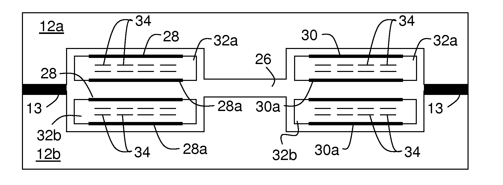
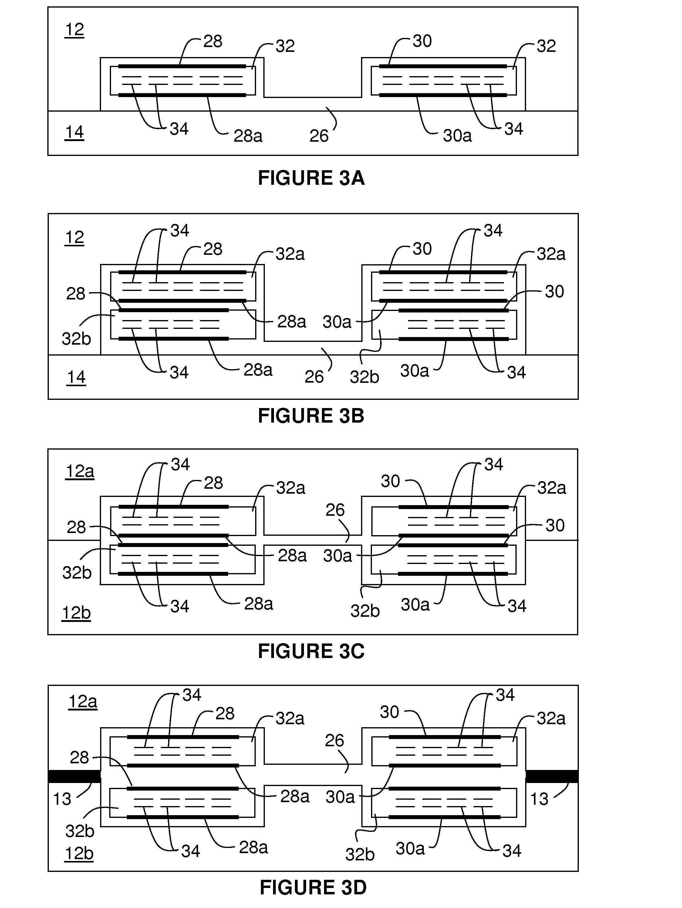
[0034]The inventors have observed that, as per the arrangements according to the invention shown in FIGS. 2 and 3, enclosing or partially enclosing windings 34 of the...


PUM

PropertyMeasurementUnit
conductiveaaaaaaaaaa
magnetic fluxaaaaaaaaaa
areaaaaaaaaaaa

Abstract

A planar transformer comprises a plurality of conductive windings provided by at least one PCB and linked by a common ferrite core passing through the or each PCB. The transformer windings are at least partially magnetically shielded from the ferrite core by a conductive non-continuous shield formed by copper planed areas on one or more of the PCB layers to improve the coupling between the windings.

Description

[0001]This invention relates to improvements in planar transformers and, more specifically but not exclusively, to a transformer with an inductance controlled by a gap in the magnetic circuit and improved coupling between windings. Such transformers are particularly useful for ion guides, particularly for use in mass spectrometers, and the improvements derived from the present invention give better control of the ions in the ion guide.BACKGROUND OF THE INVENTION[0002]A planar transformer generally consists of two or more windings formed by copper tracks, on one or more PCBs. All the windings are linked by a common ferrite core which passes through slots in the PCB. The transformer may comprise two ‘E’-core components or an ‘E’-core and an ‘I’-core.[0003]During operation when a current is injected in the windings, the magnetic flux produced by the windings will close through the magnetic material. The magnetic flux paths pass through the outer legs of the magnetic core and through th...

Claims


Application Information

Patent Timeline
Patent Type & Authority Applications(United States)
IPC IPC(8): H01F27/36
CPCH01F3/14H01F27/2804H01F27/365H01F2027/2819H01F27/367H01F27/36H01F27/363
Inventor WORTHINGTON, KENNETH R.
Owner MICROMASS UK LTD
Why Eureka
Try Eureka